Page 1 of 1
STM32F4xx Timers with no jitter
Posted: Thu Aug 11, 2016 3:21 pm
by jgriessen
I'm coding up something with this:
Code: Select all
if pyb.Pin.board.JP27.value() == 1: # in pos half-cycle
That will be quick to get the pin state, correct?
And OK to do in a ISR? Without defining any globals...whereas if renamed it would need global...
Re: STM32F4xx Timers with no jitter
Posted: Thu Aug 11, 2016 4:41 pm
by dhylands
It would be much quicker to define the pin outside the callback as a global:
and then use:
Code: Select all
if SOME_PIN.value(): # in pos half-cycle
The expression pyb.Pin.board.JP27 needs to do 4 lookups, where SOME_PIN only needs to do 1.
You also don't need the == 1, so that should reduce the generated bytecode which should also make it faster.
Re: STM32F4xx Timers with no jitter
Posted: Thu Aug 11, 2016 5:33 pm
by jgriessen
Thanks, I'll go back to
# Delay between t2ch2 init and t2ch1 init could cause out of sync?
# Or... channels have one counter in common, so they are exactly synced?
Looks like things are having delay
Re: STM32F4xx Timers with no jitter
Posted: Thu Aug 11, 2016 5:57 pm
by dhylands
2 channels on the same timer share the same counter, so they will alwys be in sync.
2 timers will only be in sync if they were zero'd at the same time, which is actually hard to do in software.
The only way I know of to ensure 2 timers are exactly in sync is to have both timers triggered by a third timer, and do the timer initialization while the 3rd timer is not counting.
If you were to enable the 2 timers using assembler you should be able to minimize the phase shift to be some 10's of nanoseconds.
Re: STM32F4xx Timers with no jitter
Posted: Thu Aug 11, 2016 6:13 pm
by jgriessen
My USB storage feature changed its name from /media/john/PYBFLASH to /media/john/4621-0000/
Is that a bad sign?
here is some code that puts out debug pulses, but nothing on JP25 JP26.
Any ideas why not? The debug2 pin goes low every other half cycle like I wanted.
The debug pin JP12, is fired from code on the OC toggling and JP27 toggles, and compared to it,
debug_pin is delayed 110 usec.
What is a way to print some values out while running on the target STM32F401?
Code: Select all
# hv_pulser.py
import pyb
from pyb import Timer
import micropython
import stm

micropython.alloc_emergency_exception_buf(100)

# Use with pyb.freq(96000000) and prescaler=11 for .125 usec timer ticks.
xfmr_pulse_period = 2800   # (x usec * 8)   Same as toggle_half_cycle duration.
xfmr_pulse_w = 900          # (x usec * 8)
pos_pulse_total = 0
pos_pulse_burstlen = 50007
neg_pulse_total = 0
neg_pulse_burstlen = 50007

# Timer 2 to give .125 usec timer ticks counting up:
t2 = pyb.Timer(2, prescaler=11, period=xfmr_pulse_period, mode=Timer.UP)

# xfmr pulse half_cycle timing.     (OC rollover callback)
# JP27 output and interrrupt.  Compare generates interrupt:
t2ch3 = t2.channel(3, pyb.Timer.OC_TOGGLE, compare=xfmr_pulse_period,
                   polarity=pyb.Timer.HIGH, pin=pyb.Pin.board.JP27)


# Define pins so they can be set with debug_pin.value() on the fly.
debug_pin = pyb.Pin('JP12', pyb.Pin.OUT_PP)
debug2_pin = pyb.Pin('JP7', pyb.Pin.OUT_PP)
pin27 = pyb.Pin.board.JP27                     # JP27 toggles every half cycle
pin26 = pyb.Pin.board.JP26
pin25 = pyb.Pin.board.JP25

# pos_half_cycle_pin                 (pin pulse drives positive going winding)
# PWM turns off output pin after xfmr_pulse_w count matches:
t2ch2 = t2.channel(2, pyb.Timer.PWM, compare=xfmr_pulse_w,
                   polarity=pyb.Timer.HIGH, pin=pyb.Pin.board.JP26)

# Delay between t2ch2 init and t2ch1 init could cause out of sync?
# Or... channels have one counter in common, so they are exactly synced?

# neg_half_cycle_pin      (pin pulse drives negative going winding)
# PWM turns off output pin after xfmr_pulse_w count matches:
t2ch1 = t2.channel(1, pyb.Timer.PWM, compare=xfmr_pulse_w,
                   polarity=pyb.Timer.HIGH, pin=pyb.Pin.board.JP25)


def t2ch3_toggle_half_cycle_cb(t2ch3):
    "PWM pulse rising edges"
    global debug_pin, debug2_pin, pin27
    if pin27.value():                   # in pos half-cycle
        debug2_pin.value(1)   # debug2
        debug_pin.value(1)
    else:                                                 # in neg half_cycle
        debug_pin.value(0)


def t2ch2_pos_wndg_fall_cb(t2ch2):
    "positive winding PWM pulse falling edge"
    global pos_pulse_total, pos_pulse_burstlen, debug2_pin, pin27
    if pin27.value():                       # pos pulse fall
        if pos_pulse_total > pos_pulse_burstlen:
            pass
        else:
            pos_pulse_total = pos_pulse_total + 1
            # disable t2ch2 output until after next half_cycle:
            # write frozen state to t2 CCMR1 reg OC2M pin JP26:
            ccmr1 = stm.mem16[stm.TIM2 + stm.TIM_CCMR1]
            ccmr1 &= 0b1000111111111111  # upcnt channel out frozen OC2M "000"
            ccmr1 |= 0b0000000000000000
            stm.mem16[stm.TIM2 + stm.TIM_CCMR1] = ccmr1
            debug2_pin.value(0)  # debug2
    else:                                             # blanked pos pulse fall
        # turn pos output back on for next time if total not met.
        # write PWM mode 1 state to t2 CCMR1 reg OC2M pin JP26:
        ccmr1 = stm.mem16[stm.TIM2 + stm.TIM_CCMR1]
        ccmr1 &= 0b1110111111111111        # upcnt channel out PWM1 OC2M "110"
        ccmr1 |= 0b0110000000000000
        stm.mem16[stm.TIM2 + stm.TIM_CCMR1] = ccmr1


def t2ch1_neg_wndg_fall_cb(t2ch1):
    "negative winding PWM pulse falling edge"
    global neg_pulse_total, neg_pulse_burstlen, pin27

    if pin27.value() == 0:                       # neg pulse fall
        if neg_pulse_total > neg_pulse_burstlen:
            pass
        else:
            neg_pulse_total = neg_pulse_total + 1
            # disable t2ch1 output until after next half_cycle:
            # write frozen state to t2 CCMR1 reg OC1M pin JP25:
            ccmr1 = stm.mem16[stm.TIM2 + stm.TIM_CCMR1]
            ccmr1 &= 0b1111111110001111  # upcnt channel out frozen OC1M "000"
            ccmr1 |= 0b0000000000000000
            stm.mem16[stm.TIM2 + stm.TIM_CCMR1] = ccmr1
    else:                                             # blanked neg pulse fall
        # turn pos output back on for next time if total not met.
        # write PWM mode 1 state to t2 CCMR1 reg OC1M pin JP25:
        ccmr1 = stm.mem16[stm.TIM2 + stm.TIM_CCMR1]
        ccmr1 &= 0b1111111111101111        # upcnt channel out PWM1 OC1M "110"
        ccmr1 |= 0b0000000001100000
        stm.mem16[stm.TIM2 + stm.TIM_CCMR1] = ccmr1


t2ch3.callback(t2ch3_toggle_half_cycle_cb)
t2ch1.callback(t2ch1_neg_wndg_fall_cb)
t2ch2.callback(t2ch2_pos_wndg_fall_cb)
Re: STM32F4xx Timers with no jitter
Posted: Thu Aug 11, 2016 7:04 pm
by dhylands
Try using pulse_width or pulse_width_ratio with pyb.Timer.PWM (it ignores the compare= field and pulse_width defaults to zero).
print statements should show up on the USB-serial line (i.e. REPL)
You only need to use global for global variables that you assign. So for example, in your t2ch3_toggle_half_cycle_cb you can remove the "global debug_pin, debug2_pin, pin27".
In t2ch2_pos_wndg_fall_cb, only pos_pulse_total needs to be declared global (because you assign to it).
Re: STM32F4xx Timers with no jitter
Posted: Thu Aug 11, 2016 7:13 pm
by jgriessen
Thanks! Got some good output finally! I was wanting to use the repl to change xfmr_pulse_w = 1900
to something else. I also have a timeout when the count goes way up, (I'm going to use that for bursts), so I want to reset from the repl.
<ctl> d resets OK.
this scope photo shows how the pulses on two pins are non overlapping, and by changing the pulse_width variable on each channel when there is no edge coming soon makes for a jitter free set of pulses on two wires. The program has a quota for pulses, after which different tactics can be used. I will make it stop pulsing both after a certain number. That needs some debugging.
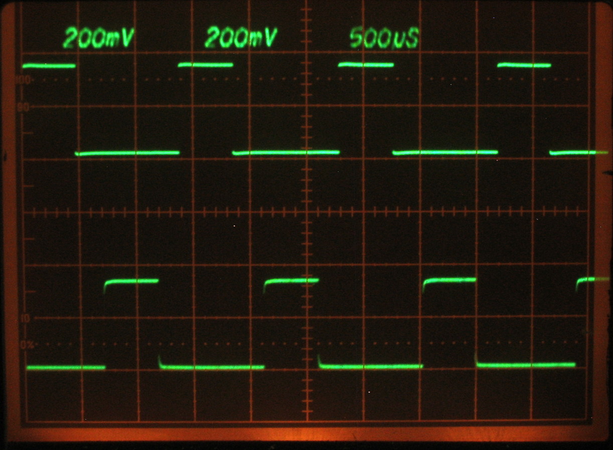
- hv_pulser-2.jpg (217.04 KiB) Viewed 7605 times
This is the code that generates the above pulses. The speed is maxed out at a cycle time of 400 microseconds, so to get faster non-jittery pulses, I think using a gated mode might skip some of the interrupts that can't be handled fast enough...
Code: Select all
# hv_pulser.py
import pyb
from pyb import Timer
import micropython
import stm

micropython.alloc_emergency_exception_buf(100)

# Use with pyb.freq(96000000) and prescaler=11 for .25 usec timer ticks.
xfmr_pulse_period = 780   # (x usec * 4)   Same as toggle_half_cycle duration.
# Cannot go much faster than this 780 period without erratic pulses.
xfmr_pulse_w = 324          # (x usec * 4)
pos_pulse_total = 0
pos_pulse_burstlen = 50007
neg_pulse_total = 0
neg_pulse_burstlen = 50007

# Timer 2 to give .125 usec timer ticks counting up:
t2 = pyb.Timer(2, prescaler=11, period=xfmr_pulse_period, mode=Timer.UP)

# xfmr pulse half_cycle timing.     (OC rollover callback)
# JP27 output and interrrupt.  Compare generates interrupt:
t2ch3 = t2.channel(3, pyb.Timer.OC_TOGGLE, compare=xfmr_pulse_period,
                   polarity=pyb.Timer.HIGH, pin=pyb.Pin.board.JP27)


# Define pins so they can be set with debug_pin.value() on the fly.
debug_pin = pyb.Pin('JP12', pyb.Pin.OUT_PP)
debug2_pin = pyb.Pin('JP7', pyb.Pin.OUT_PP)
pin27 = pyb.Pin.board.JP27                     # JP27 toggles every half cycle
pin26 = pyb.Pin.board.JP26
pin25 = pyb.Pin.board.JP25

# pos_half_cycle_pin                 (pin pulse drives positive going winding)
# PWM turns off output pin after xfmr_pulse_w count matches:
t2ch2 = t2.channel(2, pyb.Timer.PWM,  pulse_width=xfmr_pulse_w,
                   polarity=pyb.Timer.HIGH, pin=pyb.Pin.board.JP26)

#  channels have one counter in common, so they are exactly synced.

# neg_half_cycle_pin      (pin pulse drives negative going winding)
# PWM turns off output pin after xfmr_pulse_w count matches:
t2ch1 = t2.channel(1, pyb.Timer.PWM, pulse_width=xfmr_pulse_w,
                   polarity=pyb.Timer.HIGH, pin=pyb.Pin.board.JP25)


def t2ch3_toggle_half_cycle_cb(t2ch3):
    "PWM pulse rising edges"
    if pin27.value():                   # in pos half-cycle
        debug2_pin.value(1)   # debug2 JP7
        debug_pin.value(1)   # debug JP12
    else:                                                 # in neg half_cycle
        debug_pin.value(0)    # debug JP12


def t2ch2_pos_wndg_fall_cb(t2ch2):
    "positive winding PWM pulse falling edge"
    global pos_pulse_total
    if pin27.value():                       # pos pulse fall
        if pos_pulse_total > pos_pulse_burstlen:
            pass
        else:
            pos_pulse_total = pos_pulse_total + 0
            # disable t2ch2 output until after next half_cycle:
            # write frozen state to t2 CCMR1 reg OC2M pin JP26:
            ccmr1 = stm.mem16[stm.TIM2 + stm.TIM_CCMR1]
            ccmr1 &= 0b1000111111111111  # upcnt chan out frozen OC2M "000"
            ccmr1 |= 0b0000000000000000
            stm.mem16[stm.TIM2 + stm.TIM_CCMR1] = ccmr1
            debug2_pin.value(0)  # debug2  JP7
    else:                                             # blanked pos pulse fall
        # turn pos output back on for next time if total not met.
        # write PWM mode 1 state to t2 CCMR1 reg OC2M pin JP26:
        ccmr1 = stm.mem16[stm.TIM2 + stm.TIM_CCMR1]
        ccmr1 &= 0b1110111111111111       # upcnt channel out PWM1 OC2M "110"
        ccmr1 |= 0b0110000000000000
        stm.mem16[stm.TIM2 + stm.TIM_CCMR1] = ccmr1
        pass


def t2ch1_neg_wndg_fall_cb(t2ch1):
    "negative winding PWM pulse falling edge"
    global neg_pulse_total
    if pin27.value() == 0:                       # neg pulse fall
        if neg_pulse_total > neg_pulse_burstlen:
            pass
        else:
            neg_pulse_total = neg_pulse_total + 0
            # disable t2ch1 output until after next half_cycle:
            # write frozen state to t2 CCMR1 reg OC1M pin JP25:
            ccmr1 = stm.mem16[stm.TIM2 + stm.TIM_CCMR1]
            ccmr1 &= 0b1111111110001111  # upcnt channel out frozen OC1M "000"
            ccmr1 |= 0b0000000000000000
            stm.mem16[stm.TIM2 + stm.TIM_CCMR1] = ccmr1
    else:                                             # blanked neg pulse fall
        # turn pos output back on for next time if total not met.
        # write PWM mode 1 state to t2 CCMR1 reg OC1M pin JP25:
        ccmr1 = stm.mem16[stm.TIM2 + stm.TIM_CCMR1]
        ccmr1 &= 0b1111111111101111        # upcnt channel out PWM1 OC1M "110"
        ccmr1 |= 0b0000000001100000
        stm.mem16[stm.TIM2 + stm.TIM_CCMR1] = ccmr1


t2ch3.callback(t2ch3_toggle_half_cycle_cb)
t2ch1.callback(t2ch1_neg_wndg_fall_cb)
t2ch2.callback(t2ch2_pos_wndg_fall_cb)
Re: STM32F4xx Timers with no jitter
Posted: Thu Aug 11, 2016 7:48 pm
by dhylands
jgriessen wrote:My USB storage feature changed its name from /media/john/PYBFLASH to /media/john/4621-0000/
Is that a bad sign?
Are you using an SD card?
The PYBFLASH is actually a volume label, and if it got corrupted somehow, then it would use the serial number (which is the 4621-0000).
The global stuff isn't really a bug, I was just pointing out cases where it isn't needed.
Re: STM32F4xx Timers with no jitter
Posted: Thu Aug 11, 2016 8:20 pm
by jgriessen
No SD card -- just the G30TH.