undeadpony wrote:The actual questions:
Can someone help explain how to configure a pin properly and/or provide a bit more detailed/commented example? Maybe I've missed something in the docs, or it could be due to my newbie brain not having enough basic microcontroller knowledge to understand this stuff. I'm just not sure what functionality is being shown it the examples in this thread and I haven't found an example or enough of a description to figure out what the alt parameter is for. I got particularly confused from the example that sets alt = -1. I thought alt was related to the pinout alternate functions table and it's used to designate which of those functions (listed in columns labeled A-F) the pin should perform. I expected it to mean, if I want to use GP24 with PWM (to light up an LED or power a TMP36) I should set alt=5? To use GP14 with TIM_CC6 (some sort of timer function I think) then alt=12? To use a pin as just a plain GPIO I read alt=0, is that correct?
Each pin can serve multiple functions. GPIO is one mode, and one of many alternate functions is a separate mode.
To configure pin X1 as GPIO, you would use:
Code: Select all
>>> pin = pyb.Pin('X1', mode=pyb.Pin.OUT_PP)
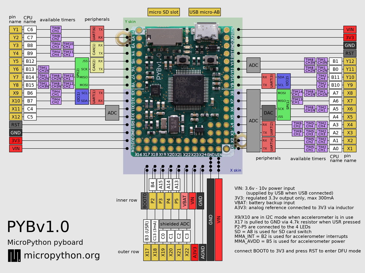
If you look at the quick reference photo for the pyboard:
http://micropython.org/resources/pybv10-pinout.jpg we can see that pin X1 can also be used for UART4, Timer 5, or Timer 2. If you call af_list() on the pin you'll see:
Code: Select all
>>> pin.af_list()
[Pin.AF1_TIM2, Pin.AF1_TIM2, Pin.AF2_TIM5, Pin.AF3_TIM8, Pin.AF7_USART2, Pin.AF8_UART4]
I'm not sure why AF1_TIM2 shows up twice, but I'll look into it. Also, it looks like Timer8 can be used and the quick reference doesn't mention that, so I'll check that out as well. If I then configure uart4, it will reconfigure pin X1 as a uart pin, and if I print the pin, we'll see that it's now configured using mode=AF_PP and af=Pin.AF8_UART4
Code: Select all
>>> uart = pyb.UART(4, 9600)
>>> pin
Pin(Pin.cpu.A0, mode=Pin.AF_PP, pull=Pin.PULL_UP, af=Pin.AF8_UART4)
Normally you don't need to mess with the alternate functions, but sometimes you do for specialty purposes. The af= parameter is ignored except when mode is AF_PP or AF_OD.
undeadpony wrote:I'm also confused about the purpose of PWM as well. My understanding is that I can use GPIO pins set to either HIGH or LOW which I thought meant a small amount of power is supplied to whatever is connected when the pin is toggled HIGH so what is the difference when using PWM? Is it just the amount of power available that is different?
PWM stands for Pulse Width Modulation, which allows the width of a pulse to be controlled. If you were to run this python code:
Code: Select all
import pyb
# At 20 kHz, the duty cycle should 50 usec
t2 = pyb.Timer(2, freq=20000, mode=pyb.Timer.PWM)
ch1 = t2.channel(1, pyb.Timer.PWM, pin=pyb.Pin.board.X1, pulse_width_percent=5)
ch2 = t2.channel(2, pyb.Timer.PWM, pin=pyb.Pin.board.X2, pulse_width_percent=35)
ch3 = t2.channel(3, pyb.Timer.PWM, pin=pyb.Pin.board.X3, pulse_width_percent=50)
ch4 = t2.channel(4, pyb.Timer.PWM, pin=pyb.Pin.board.X4, pulse_width_percent=95)
and do a logic analyzer capture you would see something like this:
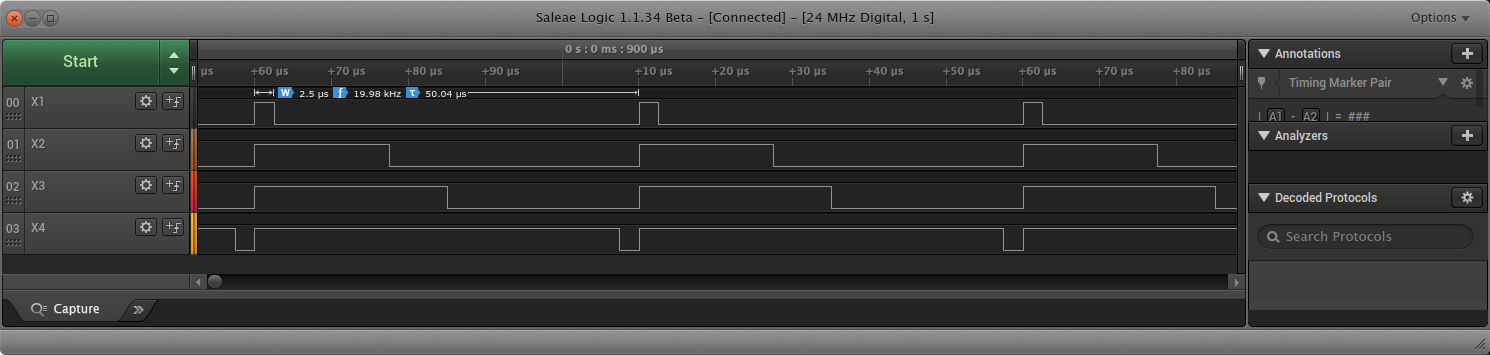
The frequency of 20kHz means that the duty cycle will be 50 usec. At 5% PWM, the signal will be high for 5% of the 50 usec (2.5usec) and low for 95% (47.5 usec).
X2 shows a PWM signal with a pulse width of 35%. X3 shows 50% and X4 shows 95%. A PWM of 0% is equivalent to setting the pin low, and a PWM of 100% is equivalent to setting the pin high.
Normally, you would use PWM to control the speed of a motor, or the brightness of an LED. The nice thing about having the hardware generate the PWM, is that once you set it, it just keeps repeating the pulse over and over (you can see 2 full cycles plus the start of a 3rd int he photo).
undeadpony wrote:One last question, in the docs I didn't notice that there were any default settings for 'mode', 'pull', 'drive', or 'alt'. If I do this:
Code: Select all
from machine import Pin
myPin = machine.Pin('GP11')
how will the pin behave?
That will return an uninitialized pin object. Looking at the documentation for pin.init:
http://docs.micropython.org/en/latest/l ... l#pin.init we can see that there is no default for mode, pull defaults to Pin.PULL_NONE, and af defaults to -1. Looking at the WiPy documentation:
http://micropython.org/resources/docs/e ... l#pin.init the defaults seem to be missing. Looking at the code
https://github.com/micropython/micropyt ... pin.c#L534, it appears that the defaults are as follows: mode=Pin.IN, pull=None, drive=Pin.MED_POWER (4mA), alt=-1
The Pololu A4988 stepper driver has 2 inputs, a step signal, and dir signal. If you were to connect STEP up to GP11 and DIR to GP12, then you could drive it using something like:
Code: Select all
from machine import Pin
import time
step = Pin('GP11', mode=Pin.OUT)
dir = Pin('GP12', mode=Pin.OUT)
dir.value(0)
for i in range(1000):
    step.value(0)
    time.sleep_us(1000)
    step.value(1)
    time.sleep_us(1000)
that should make the stepper rotate 5 times (assuming its configured for full step mode) in about 2 seconds. If you had 1/16 microsteps then you'd need to change the range(1000) to 16000 and change the delay to time.sleep_us(63) and you should get the same 5 revolutions in approx 2 seconds.

