Hello again.
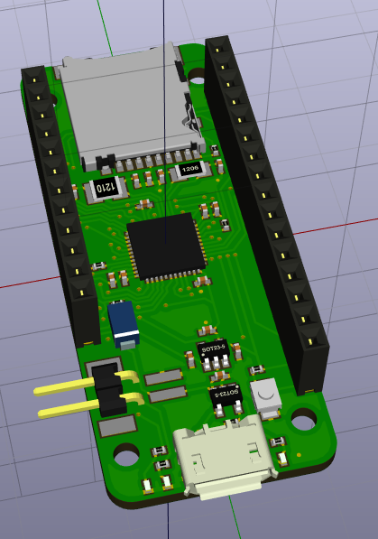
I've got your design files open in KiCad to see if I could maybe figure out why your charge controller burned out.
The only problem I see is that when you're on battery power the VDD input on the charger chip is brought to VBAT minus the forward voltage drop of D2. The datasheet specifies the recommended minimum supply voltage (VDD) as Vreg + 0.3V. Seeing as the battery voltage is probably less than the regulation voltage and VDD is a diode drop below that it appears that you're not in recommended operating conditions.
To remedy, I'd place a second diode between your VBUS net and the input on the
regulator IC. I'd also put a pull-down on the CE input to the
charge controller to give the charge LED current a path to ground and to ensure the charger IC is disabled when your 5V USB power is absent.
I've attached a jpeg of my changes to your schematic for reference.
edit: cropped full schematic to show changes only
edit again: change wording to match diagram
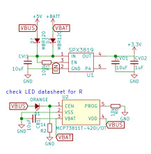
- Feather-Pyboard-changes.sch.jpg (17.31 KiB) Viewed 9561 times