No I2C feedback: How to debug?

Discuss development of drivers for external hardware and components, such as LCD screens, sensors, motor drivers, etc.
Target audience: Users and developers of drivers.
User avatar
wintifrosch
Posts: 12
Joined: Sun Mar 20, 2022 9:37 am
Location: Winterthur, Switzerland
Contact:

No I2C feedback: How to debug?

Post by wintifrosch » Thu Apr 28, 2022 7:18 pm

I connected a PN532 NFC board to my RaspberryPi Pico. Since there's no Micropython Library supporting I2C, I tried to port the Adafruit_CircuitPython_PN532, motivated by @Roberthh here in this Micropython Forum: «I have ported adafruit libraries a few times, and it was not difficult.» and mimicking the SPI port of @cgglzpy «I've actually done this».
My Problem: I can send data with my code fragment, but I don't receive an answer ("Failed to detect the PN532"). How would you geeks proceed?
What I have done:
  • The writing on the chip of my board seem identical to all pictures I can find on the internet. ➝ I am confident that it is an original chip.
  • The DIP Switches are configured to I2C as requested. While NXPs PN532 User Guide states in chap. 6.1.1.3 I2C interface the I2C address to be 0x48, there is no mention that the address is shifted one byte in the I2C protocol (and thus, 0x24 must be used). And the board should be «able to support a clock frequency up to 400 kHz».
  • An "i2c.scan()" states the board's address not reliably (~50% success). Lowering the I2C frequency tend to improve success, but still far from reliable. Same with additional 100kΩ pull-up resistors.
  • I tried to improve communication by adding IRQ and Reset lines, to reliably reset and wake up the board, but without noticeable improvement.
Possible next steps:
  • Try the second board I ordered from AliExpress. ➝ I don't expect different results.
  • Verify Hardware and Wiring: Reconfigure the Pico to use CircuitPython and try the Adafruit's Library. ➝ Since I never tried circuitPython I'd budget several hours for that test.
  • Use the problems described above as an excuse to invest in a simple logic analyzer (i.e. LA104 for ~100 USD). ➝ Probably not very helpful for the current problem, but a nice investment 😎.
Any tips, mates?

User avatar
karfas
Posts: 193
Joined: Sat Jan 16, 2021 12:53 pm
Location: Vienna, Austria

Re: No I2C feedback: How to debug?

Post by karfas » Fri Apr 29, 2022 5:25 am

Unless you get a reliable i2c.scan() result, any other communication will most likely fail. The address "shifted by 1 bit" might also indicate you lose data during receive.

If you use 100k pullups you can as well go with the ESP32 internal pullup (~10k...70k).
Here in the forum I have seen recommendations for 4.7k for the I2C bus.

Good Luck!
A few hours of debugging might save you from minutes of reading the documentation! :D
My repositories: https://github.com/karfas

User avatar
dhylands
Posts: 3821
Joined: Mon Jan 06, 2014 6:08 pm
Location: Peachland, BC, Canada
Contact:

Re: No I2C feedback: How to debug?

Post by dhylands » Sat Apr 30, 2022 4:44 am

The shifted by one bit is common issue that many people misunderstand.

The I2C address is a 7-bit address and is stored up the upper 7-bits of the "address byte". The lower bit is a read/write bit.

This is described in the SMBUS protocol: http://smbus.org/specs/smbus20.pdf If you look on page 28 you can see the start-bit, the 7 address bits, and the Wr bit. Page 24 describes the address as being 7-bits,

Some datasheets describe the 7-bit address, and some data sheets desribe an 8-bit address with separate read and write addresses. This doesn't help things.

When you do a bus scan using i2c.scan() it reports the 7-bit address, and when you print that array in python it prints numbers in decimal (i.e. base 10), and not the 8-bit address byte which includes the read/write bit, Most datasheets report their address in hexadecimal (base 16).

User avatar
wintifrosch
Posts: 12
Joined: Sun Mar 20, 2022 9:37 am
Location: Winterthur, Switzerland
Contact:

Re: No I2C feedback: How to debug?

Post by wintifrosch » Sat Apr 30, 2022 11:23 am

@karfas: «Unless you get a reliable i2c.scan() result, any other communication will most likely fail.»
➝ fair point! I'll suspend solving the address issue until electrical issues are under control.

Adding 4.7kΩ pull-ups seemed to help, but still far from reliable.
➝ As ist seems, repeated i2c.scan() suck the power out of the supply line:

Code: Select all

>>>> i2c = I2C(0, sda=sda, scl=scl, freq=100_000)
     results=[]
     for x in range(20):
         results.append(i2c.scan())
         sleep(0.2)
     print(results)
[[36], [36], [36], [36], [], [], [], [], [], [], [], [], [], [], [], [], [], [], [], []]
➝ Maybe the board must be operated @5V? – The NXP PN532/C1 product data sheet says on p.2 «2.7 to 5.5 V power supply operating range», and the sellers feature description states: «9.On-board level shifter, Standard 5V TTL for I2C and UART, 3.3V TTL SPI».

Is it dangerous to test the board @5V? – Since SDA is HIGH when idle (see pic below), I can measure the output with my simple volt meter, without connecting SDA and SCL to the PICO.
➝ Indeed, idle SDA is +2.6V, even if I supply the board with +5V. (same for idle SCL)
Image

I risked trying.
With i2c frequency 10_000 I have better results than ever. Quality not depending on the pull-up resistors but on i2c frequency and test interval delay:

Code: Select all

>>> from time import sleep
    iterations=12
    for freq in [5_000,10_000,20_000,40_000,80_000]:
        i2c = I2C(0, sda=sda, scl=scl, freq=freq)
	for delay in [0.05, 0.1, 0.2, 0.4, 0.8]:
            results=[]
            start = time.time()
            for x in range(iterations):
                results.append(i2c.scan())
                sleep(delay)
            realdelay = (time.time() - start) / iterations
            print('delay='+'{:>4,.2f}'.format(delay),'(real:'+'{:>6,.4f}'.format(realdelay)+'s)','freq='+'{:>6,}'.format(freq).replace(',','_')+':',results)
        print()
    
delay=0.05 (real:0.3333s) freq= 5_000: [[36], [36], [36], [36], [36], [36], [36], [36], [36], [36], [36], [36]]
delay=0.10 (real:0.4167s) freq= 5_000: [[36], [36], [36], [36], [36], [36], [36], [36], [36], [36], [36], [36]]
delay=0.20 (real:0.5000s) freq= 5_000: [[36], [36], [36], [36], [36], [36], [36], [36], [36], [36], [36], [36]]
delay=0.40 (real:0.6667s) freq= 5_000: [[36], [36], [36], [36], [36], [36], [36], [36], [36], [36], [36], [36]]
delay=0.80 (real:1.1667s) freq= 5_000: [[36], [36], [36], [36], [36], [36], [36], [36], [36], [36], [36], [36]]

delay=0.05 (real:0.1667s) freq=10_000: [[36], [36], [36], [36], [36], [36], [36], [36], [36], [36], [36], [36]]
delay=0.10 (real:0.2500s) freq=10_000: [[36], [36], [36], [36], [36], [36], [36], [36], [36], [36], [36], [36]]
delay=0.20 (real:0.4167s) freq=10_000: [[36], [36], [36], [36], [36], [36], [36], [36], [36], [36], [36], [36]]
delay=0.40 (real:0.5000s) freq=10_000: [[36], [36], [36], [36], [36], [36], [36], [36], [36], [36], [36], [36]]
delay=0.80 (real:1.0000s) freq=10_000: [[36], [36], [36], [36], [36], [36], [36], [36], [36], [36], [36], [36]]

delay=0.05 (real:0.0833s) freq=20_000: [[36], [36], [36], [36], [36], [36], [36], [36], [36], [36], [36], [36]]
delay=0.10 (real:0.1667s) freq=20_000: [[36], [36], [36], [36], [36], [36], [36], [36], [36], [36], [36], [36]]
delay=0.20 (real:0.3333s) freq=20_000: [[36], [36], [], [36], [], [36], [], [36], [], [36], [], [36]]
delay=0.40 (real:0.5000s) freq=20_000: [[36], [36], [36], [36], [], [36], [], [36], [], [36], [], [36]]
delay=0.80 (real:0.8333s) freq=20_000: [[36], [36], [36], [36], [36], [36], [36], [36], [36], [36], [36], [36]]

delay=0.05 (real:0.0833s) freq=40_000: [[], [36], [36], [36], [36], [36], [36], [36], [36], [36], [36], [36]]
delay=0.10 (real:0.1667s) freq=40_000: [[36], [36], [], [], [], [], [], [], [], [], [], []]
delay=0.20 (real:0.2500s) freq=40_000: [[], [], [36], [36], [36], [36], [36], [36], [36], [36], [36], [36]]
delay=0.40 (real:0.4167s) freq=40_000: [[36], [], [36], [36], [36], [36], [36], [36], [36], [36], [36], [36]]
delay=0.80 (real:0.8333s) freq=40_000: [[36], [36], [], [], [], [], [], [], [], [], [], []]

delay=0.05 (real:0.0833s) freq=80_000: [[36], [36], [], [], [], [], [], [], [], [], [], []]
delay=0.10 (real:0.0833s) freq=80_000: [[36], [36], [], [], [], [], [], [], [], [], [], []]
delay=0.20 (real:0.2500s) freq=80_000: [[], [36], [36], [36], [36], [36], [36], [36], [36], [36], [36], [36]]
delay=0.40 (real:0.4167s) freq=80_000: [[], [], [36], [36], [36], [36], [36], [36], [36], [36], [36], [36]]
delay=0.80 (real:0.8333s) freq=80_000: [[36], [36], [], [], [], [], [], [], [], [], [], []]
How can I further improve my results?
Last edited by wintifrosch on Sat Apr 30, 2022 4:29 pm, edited 1 time in total.

Online
User avatar
Roberthh
Posts: 3667
Joined: Sat May 09, 2015 4:13 pm
Location: Rhineland, Europe

Re: No I2C feedback: How to debug?

Post by Roberthh » Sat Apr 30, 2022 4:12 pm

The observation that power drops with higher clock frequencies seems strange. So you
- use 4k7 pull-up resistors to Vcc?
- have connected GND, SDA and SCL?
- the wires between Pico and sensor are short, <30 cm ?
- there are no other capacitive loads on SDA, SCL?

User avatar
wintifrosch
Posts: 12
Joined: Sun Mar 20, 2022 9:37 am
Location: Winterthur, Switzerland
Contact:

Re: No I2C feedback: How to debug?

Post by wintifrosch » Sat Apr 30, 2022 4:39 pm

@Roberthh: I modified the test protocol above while you were posting your answer.
If you look at real delay difference with long delays, every i2c.scan() obviously takes 0.05–0.16s. In iterations with short delays I might step into previous i2c.scan() communication?

In response to your questions:
  • Yes, the tests above are all with 4.7kΩ to +3.3V.
  • Yes, VCC=+5V, GND, SDA and SCL are connected nicely.
  • Yes, the wires between Pico and sensor are <10 cm.
  • No, there are no other capacitive loads on SDA and SCL.
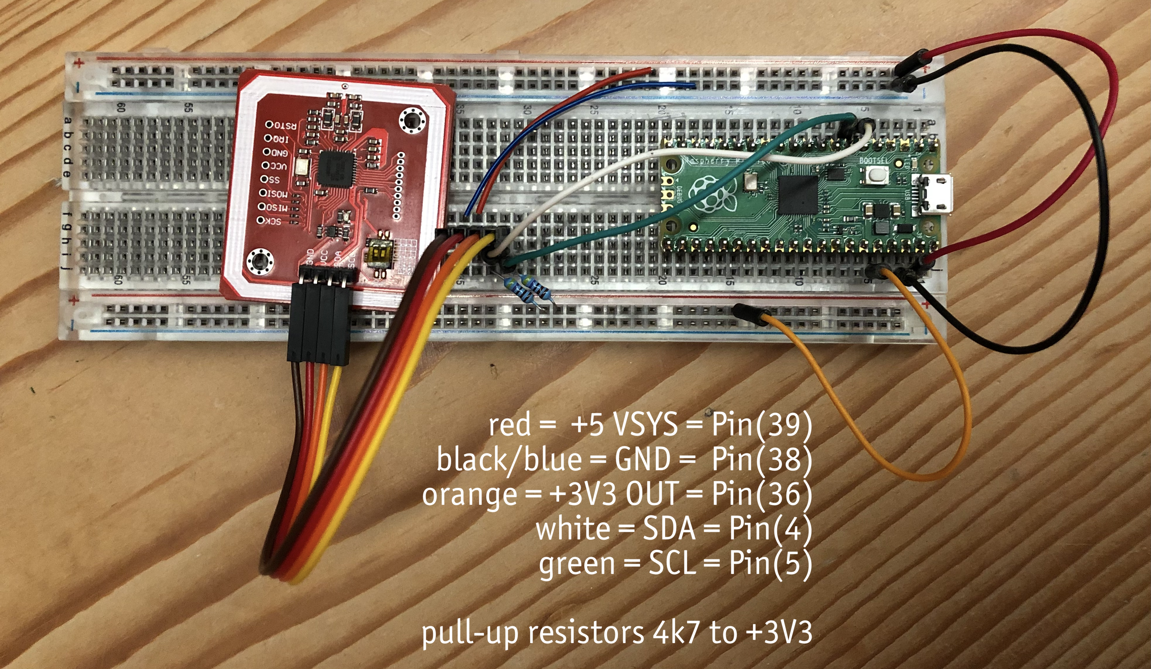
However, I created a new clean breadboard and received the results below (same Pico, same RF532 board):
Image

Code: Select all

>>> from machine import Pin, I2C
    import time
    sda=Pin(4)
    scl=Pin(5)
    iterations=12
    for freq in [6_250,12_500,25_000,50_000,100_000,200_000,400_000]:
        i2c = I2C(0, sda=sda, scl=scl, freq=freq)
        for delay in [0.05, 0.1, 0.2, 0.4, 0.8, 1.6, 3.2]:
            results=[]
            start = time.time()
            for x in range(iterations):
                results.append(i2c.scan())
                time.sleep(delay)
            realdelay = (time.time() - start) / iterations
            print('delay='+'{:>4,.2f}'.format(delay),'(real:'+'{:>6,.4f}'.format(realdelay)+'s)','freq='+'{:>6,}'.format(freq).replace(',','_')+':',results)
        print()

delay=0.05 (real:0.3333s) freq= 6_250: [[36], [36], [36], [36], [], [], [], [], [], [], [], []]
delay=0.10 (real:0.3333s) freq= 6_250: [[], [36], [36], [36], [36], [], [36], [], [36], [], [36], []]
delay=0.20 (real:0.4167s) freq= 6_250: [[36], [36], [], [36], [36], [], [36], [36], [], [36], [36], [36]]
delay=0.40 (real:0.6667s) freq= 6_250: [[], [36], [36], [], [36], [36], [], [36], [36], [], [36], [36]]
delay=0.80 (real:1.0833s) freq= 6_250: [[36], [36], [], [36], [], [36], [36], [], [36], [], [36], [36]]
delay=1.60 (real:1.8333s) freq= 6_250: [[36], [36], [36], [36], [36], [36], [36], [36], [36], [36], [36], [36]]
delay=3.20 (real:3.4167s) freq= 6_250: [[36], [36], [36], [36], [], [], [36], [36], [36], [36], [36], []]

delay=0.05 (real:0.1667s) freq=12_500: [[36], [], [36], [36], [], [36], [36], [], [36], [], [36], []]
delay=0.10 (real:0.2500s) freq=12_500: [[36], [36], [36], [36], [36], [36], [36], [36], [36], [36], [36], [36]]
delay=0.20 (real:0.3333s) freq=12_500: [[36], [], [36], [], [36], [36], [], [36], [], [], [36], [36]]
delay=0.40 (real:0.5000s) freq=12_500: [[], [], [], [], [], [], [], [], [], [], [], []]
delay=0.80 (real:0.9167s) freq=12_500: [[], [], [36], [36], [36], [36], [], [], [36], [36], [36], [36]]
delay=1.60 (real:1.7500s) freq=12_500: [[36], [36], [], [36], [36], [36], [36], [], [36], [36], [], [36]]
delay=3.20 (real:3.3333s) freq=12_500: [[36], [36], [], [], [], [36], [36], [36], [36], [], [], []]

delay=0.05 (real:0.0833s) freq=25_000: [[], [36], [36], [], [36], [36], [], [], [36], [36], [], []]
delay=0.10 (real:0.1667s) freq=25_000: [[36], [], [36], [36], [], [36], [36], [], [36], [], [], [36]]
delay=0.20 (real:0.2500s) freq=25_000: [[], [36], [], [36], [36], [], [36], [36], [], [36], [36], []]
delay=0.40 (real:0.5000s) freq=25_000: [[36], [], [], [36], [36], [], [], [36], [36], [], [], [36]]
delay=0.80 (real:0.8333s) freq=25_000: [[36], [], [36], [36], [36], [36], [36], [36], [], [36], [36], [36]]
delay=1.60 (real:1.6667s) freq=25_000: [[], [], [], [36], [36], [36], [36], [36], [36], [], [36], [36]]
delay=3.20 (real:3.2500s) freq=25_000: [[], [36], [36], [36], [], [36], [36], [36], [], [], [36], [36]]

delay=0.05 (real:0.0833s) freq=50_000: [[36], [36], [], [36], [36], [], [], [36], [36], [], [36], [36]]
delay=0.10 (real:0.1667s) freq=50_000: [[], [36], [36], [36], [36], [36], [36], [36], [36], [36], [36], [36]]
delay=0.20 (real:0.2500s) freq=50_000: [[36], [36], [], [36], [36], [36], [], [36], [36], [], [], [36]]
delay=0.40 (real:0.4167s) freq=50_000: [[36], [36], [36], [], [], [36], [36], [36], [36], [36], [], []]
delay=0.80 (real:0.8333s) freq=50_000: [[36], [], [], [], [], [], [], [], [36], [36], [36], [36]]
delay=1.60 (real:1.6667s) freq=50_000: [[36], [], [36], [], [36], [], [36], [36], [36], [36], [], [36]]
delay=3.20 (real:3.1667s) freq=50_000: [[36], [], [36], [], [36], [36], [], [36], [36], [], [36], []]

delay=0.05 (real:0.0833s) freq=100_000: [[], [], [], [], [], [], [], [], [], [], [], []]
delay=0.10 (real:0.1667s) freq=100_000: [[], [36], [36], [36], [], [36], [36], [36], [], [36], [36], [36]]
delay=0.20 (real:0.1667s) freq=100_000: [[], [], [], [], [], [], [], [], [], [], [], []]
delay=0.40 (real:0.4167s) freq=100_000: [[], [36], [36], [], [36], [36], [], [36], [36], [], [36], [36]]
delay=0.80 (real:0.8333s) freq=100_000: [[], [36], [36], [36], [36], [36], [36], [36], [36], [], [], [36]]
delay=1.60 (real:1.6667s) freq=100_000: [[36], [], [], [36], [36], [], [36], [36], [], [36], [36], []]
delay=3.20 (real:3.1667s) freq=100_000: [[], [], [], [36], [36], [36], [], [], [], [], [36], [36]]

delay=0.05 (real:0.0833s) freq=200_000: [[], [36], [36], [36], [], [36], [36], [36], [36], [], [36], [36]]
delay=0.10 (real:0.0833s) freq=200_000: [[36], [36], [36], [36], [36], [36], [], [36], [], [36], [36], [36]]
delay=0.20 (real:0.2500s) freq=200_000: [[36], [36], [], [36], [36], [36], [], [36], [36], [36], [], [36]]
delay=0.40 (real:0.4167s) freq=200_000: [[36], [36], [], [36], [36], [], [36], [36], [], [36], [36], []]
delay=0.80 (real:0.8333s) freq=200_000: [[], [36], [], [36], [], [36], [], [36], [], [36], [], [36]]
delay=1.60 (real:1.5833s) freq=200_000: [[], [], [], [], [], [], [], [], [], [], [], []]
delay=3.20 (real:3.1667s) freq=200_000: [[36], [36], [36], [36], [36], [36], [36], [], [36], [36], [36], [36]]

delay=0.05 (real:0.0833s) freq=400_000: [[36], [36], [36], [36], [], [36], [36], [], [36], [36], [], [36]]
delay=0.10 (real:0.0833s) freq=400_000: [[36], [36], [36], [36], [36], [36], [36], [], [], [], [], []]
delay=0.20 (real:0.2500s) freq=400_000: [[36], [], [36], [36], [], [], [36], [36], [], [], [36], [36]]
delay=0.40 (real:0.4167s) freq=400_000: [[36], [36], [36], [36], [36], [36], [36], [36], [36], [36], [36], [36]]
delay=0.80 (real:0.7500s) freq=400_000: [[36], [36], [36], [], [], [], [], [], [], [], [], []]
delay=1.60 (real:1.6667s) freq=400_000: [[], [36], [], [36], [], [36], [], [36], [], [36], [], [36]]
delay=3.20 (real:3.1667s) freq=400_000: [[], [36], [36], [36], [36], [], [36], [], [36], [36], [36], [36]]
Last edited by wintifrosch on Sat Apr 30, 2022 7:00 pm, edited 1 time in total.

Online
User avatar
Roberthh
Posts: 3667
Joined: Sat May 09, 2015 4:13 pm
Location: Rhineland, Europe

Re: No I2C feedback: How to debug?

Post by Roberthh » Sat Apr 30, 2022 6:56 pm

There is no buffering in I2C scan. It just tries one address after the other. It could the a thermal problem. The current drawn by the RFC module is up to 200 mA. The 3.3V regulator of the Pico should be able to supply these. Did you say previously that Vcc decreases during your tests? Can you test it?

User avatar
wintifrosch
Posts: 12
Joined: Sun Mar 20, 2022 9:37 am
Location: Winterthur, Switzerland
Contact:

Re: No I2C feedback: How to debug?

Post by wintifrosch » Sat Apr 30, 2022 7:08 pm

@Roberthh: «Vcc decreases during your tests? Can you test it?»
➝ I don't think so. I only have an old bulky CALTEK CM2700 multimeter.

« a thermal problem»
➝ no smell in a 30' test, no excess temp registered with my finger on any of the components on the two boards.

Have you seen the VERY DIFFERENT results in my last post above?

Is it dangerous to connect a separate power supply to the breadboard, in parallel to USB? This could stabilise the power.
Or some capacitors to the 3V3?

Online
User avatar
Roberthh
Posts: 3667
Joined: Sat May 09, 2015 4:13 pm
Location: Rhineland, Europe

Re: No I2C feedback: How to debug?

Post by Roberthh » Sat Apr 30, 2022 8:00 pm

The Multimeter looks fine. It will stiil tell you, if Vcc is 3.3V or 3V. My favorite Multimeter is 40 years old.
Thermal problem does not mean that it burns your finger.
Edit: No. there seem no real difference between the various frequencies. That would rule out basic timing problems. And yes, you can supply the RFID reader with a separate power supply, as long as the GND levels are the same.
P.S.: Excellent picture!

User avatar
wintifrosch
Posts: 12
Joined: Sun Mar 20, 2022 9:37 am
Location: Winterthur, Switzerland
Contact:

Re: No I2C feedback: How to debug?

Post by wintifrosch » Sat Apr 30, 2022 8:48 pm

My favorite multimeter is 40 years old.
➝ same :D The display cover glass is VERY yellowish.
➝ I'd expect only short fluctuations during a test, and therefore I didn't even try it.

It will still tell you, if Vcc is 3.3V or 3V.
➝ The 3V3 line is 3.26V idle without noticeable drop during a test with freq=100_000 and delay=0.04. Seems ok to me. Is this too low?

Excellent picture!
➝ thx! :geek:

VERY DIFFERENT results
➝ I meant to address the very different results between the two boards. The difference might come from a 470µF capacitor on the VCC 5V, before a servo.

I'll try the external PS

Post Reply