Page 3 of 3

Re: So you want to use the UART...

Posted: Tue Mar 21, 2017 5:50 pm
by dhylands
GPS devices typically have a pure ASCII mode and deliver NMEA sentences:
http://www.gpsinformation.org/dale/nmea.htm

Many devices also support a binary mode where they'll send binary packets. This allows for faster updates. However the binary protocols tend to differ from manufacturer to manufacturer.

There is often a command to switch between NMEA mode and binary mode, and this typically persists across power cycles.

gpsd includes log files from a ton of different GPSes if you're looking for typical data streams:
http://git.savannah.gnu.org/cgit/gpsd.g ... est/daemon

Re: So you want to use the UART...

Posted: Tue Mar 21, 2017 7:09 pm
by BetterAutomations
[quote="pythoncoder"]The circuit is to ensure that the logic levels supplied to the ESP8266 don't exceed 3.3V.[/quote]

Hmm? Per the opening post, the circuit is to provide a non-blocking read. My question is whether it's required to send data into the ESP from another device such as a Pi.

Re: So you want to use the UART...

Posted: Wed Mar 22, 2017 7:26 am
by pythoncoder
BetterAutomations wrote:... Per the opening post, the circuit is to provide a non-blocking read. My question is whether it's required to send data into the ESP from another device such as a Pi.
I thought you were referring to the circuit in the post from @mflmartin, rather than the one in the OP.

The circuit in the OP is effectively a logic gate which is being used to prevent the ESP8266 from transmitting spurious data. The GPIO pin can force the Tx out to a high state regardless of the output of the UART transmitter.

Neither circuit provides a non-blocking read.

If you are sending data from a device with 5V logic levels to the ESP8266, a logic level converter should be used because the ESP8266 pins are not 5V tolerant.

Re: So you want to use the UART...

Posted: Thu Mar 23, 2017 3:28 am
by BetterAutomations
Right. So is that circuit required when the ESP will be listening for a command? I wouldn't think so since it's on the TX line but I want to confirm.

Re: So you want to use the UART...

Posted: Thu Mar 23, 2017 7:38 am
by pythoncoder
If you are only listening all you need is a logic level converter on the RXD line to protect the ESP8266 from 5V.

Re: So you want to use the UART...

Posted: Sat Jul 22, 2017 12:32 pm
by snaky1
hello

i think i am trying to do the same thing(use wemos d1 board in Tristate/Uart mode?), but my external device has 5volts input, but it is said that the data transfers at 3,3volts between the external device and the Uart adapter(wemos) - so do i just connect the Reset and Ground pin on the board and then connect the device Tx to wemos Rx and device Rx to wemos Tx and everything should work just fine?(plus a wire from wemos 5V to device 5V input)
Like the wemos d1 r2 board will work in this Uart mode and i need to use this 'crossover cable' to make everything safe and not burn anything down?:x

thanks

Re: So you want to use the UART...

Posted: Sat Aug 19, 2017 9:30 pm
by snaky1
so i basically got it working now, but i had to connect Rx to Rx and Tx to Tx, which probably means that this is how the arduino board works in the plain uart mode...

Re: So you want to use the UART...

Posted: Sun Aug 20, 2017 4:45 pm
by crizeo
I wanted to use the UART as well to get some information from a GPS module. But is it even possible to use UART for communicating with another module? UART(1) does not make any sense, so I can only use UART(0). The problem with UART(0) is that when I connect the GPS module, it will simply print all the data to the console. How can I use the read method instead?

That's what I get on WebREPL (I don't even have to create the UART object); PuTTy not working with UART in use:
gps.png
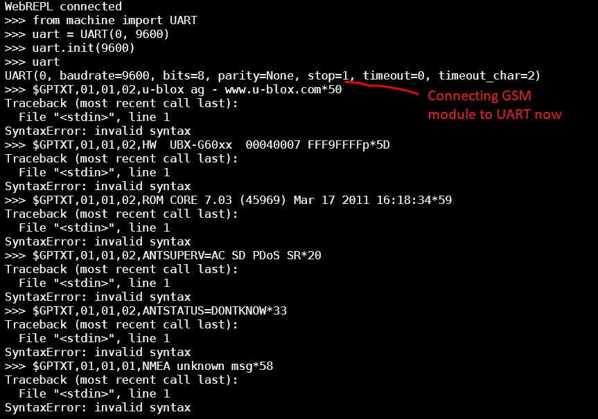
gps.png (45.26 KiB) Viewed 9708 times
Update: Couldn't get it work so I used software serial provided by some really nice guy (watch here!). If you want to use SoftUART have a look at this firmware modification, which includes a SoftUART class in the machine module. If you don't want to build the firmware yourself, here is a compiled version that works for me: firmware-softuart.bin

Code: Select all

import machine
su = machine.SoftUART(machine.Pin(13), machine.Pin(12), baudrate=9600)  # first is TX, second RX
while True:
    print(su.readline())  # usage similar to machine.UART
Update 2: Got UART0 working now. You cannot use PuTTy/ampy when using UART0 for another device. You will first have to setup everything (wlan and WebREPL if required later). You can put your code (where you read from uart0) in main.py or in another file (that has to be run from WebREPL then), but you cannot use the standard output (I think). That's why I connected a small oled display for output. My working test code (using a NEO 6M GSM module connected via RX/TX and a 128x64 OLED display (you will need ssd1306.py from Adafruit as well) connect via SCL/SDA):

Code: Select all

# main.py
import machine, utime
import ssd1306

class Display:
    def __init__(self, width=128, height=64, scl=5, sda=4):
        self._width = width
        self._height = height
        self.oled = ssd1306.SSD1306_I2C(self._width, self._height,
                                        machine.I2C(-1, machine.Pin(scl), machine.Pin(sda)))
        self.clear()

    def clear(self):
        self.oled.fill(0)
        self.oled.show()
        
    def println(self, msg: str):
        self.oled.scroll(0, -8)
        self.oled.framebuf.fill_rect(0, self._height-8, self._width, 8, 0)  # clear last line
        self.oled.text(msg, 0, self._height-8)
        self.oled.show()

class GPSModule:
    def __init__(self):
        self.module = machine.UART(0, 9600)
        self.module.init(9600)

    def next(self):
        ret = self.module.read(1)#.decode()
        return b'\x00' if ret is None else ret

def main():
    display = Display()
    display.println("#### START! ####")
    gps = GPSModule()
    while True:
        try:
            display.println(str(ord(gps.next())))
        except Exception as ex:
            display.println("ERR: %s" % repr(ex))
            utime.sleep(1)
            display.println("     %s" % ex.args[0])
            break
        except KeyboardInterrupt:
            display.println("ERR: INTERRUPTED")
            break
        except:
            display.println("ERR!")
            break

if __name__ == "__main__":
    main()

Update 3: Another problem happens when the module connected on UART0 sends b'\x03' which means CTRL+C, you will get an KeyboardInterrupt then. I saw that there may be a function to disable keyboard interrupts (micropython.kbd_intr(-1)), but in my version (1.8.6) I had to disable keyboard interrupts manually (see here). My module is able to send 0x03 without any interrupts. And the best thing is: You will still be able to connect via WebREPL (if activated before using import webrepl_setup) and you'll see the keys pressed immediately on the screen (but not in WebREPL). You're also able to send an interrupt (CTRL+C) there which will still cause an KeyboardInterrupt.

Re: So you want to use the UART...

Posted: Mon Jun 18, 2018 1:03 pm
by ali3tareh
the file firmware-softuart.bin dose not exist,would you please add it agian.thanks.

Re: So you want to use the UART...

Posted: Wed Jun 20, 2018 4:30 pm
by crizeo
I updated the link, there you go: firmware186-softuart.bin But note that this is still based on MicroPython version 1.8.6. Someone would have to do the changes listed here to the current version. Interrupts (CTRL+C) are enabled in this version, so this is basically version 1.8.6 with the machine.SoftUART class.

Edit: Updated link. Seems like somebody ported the changes to the current version of micropython. Have a look at this post.