Page 1 of 2
ESP12F Minimum Serial Wiring
Posted: Wed Oct 09, 2019 2:58 am
by PsuFan
Hello,
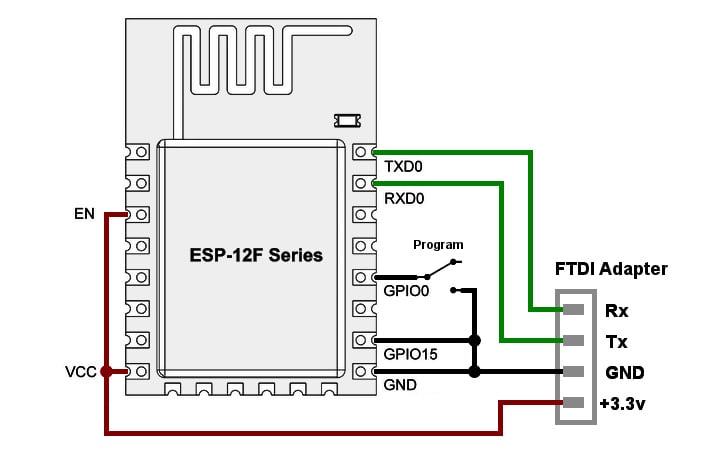
What are the minimum wiring for serial MicroPython Repl? Diagrams are all over the place on needing different resistors and pulling up GPIO0 and GPIO2. Some pull up RST, some don't, etc. Where is the official spec, what is actually needed? I am able to get into flash mode and have erased and flashed MicroPython twice, but I cannot get into the Repl. I cannot get any printable characters on reset on any baud (9600, 115200, ~76800?)

Thanks,
PsuFan
Re: ESP12F Minimum Serial Wiring
Posted: Wed Oct 09, 2019 6:15 am
by Roberthh
Looking at the schematics of a Wemos D1 mini, it matches your second wiring. So maybe you could just try to swap RX and TX. The labeling on USB/UART adapters is not always consistent.
Re: ESP12F Minimum Serial Wiring
Posted: Wed Oct 09, 2019 1:08 pm
by PsuFan
Would I be able to upload a firmware (getting the chip type, mac, flash size, setting baud, etc) having the rx/tx swapped? I've verified USB wiring on board printing itself. (I had to solder power to 3.3v pad)
Re: ESP12F Minimum Serial Wiring
Posted: Wed Oct 09, 2019 1:44 pm
by Roberthh
You said that you sucessfully loaded the firmware to the device. Then Tx and RX are right. No need to swap.
Do you get any response in the terminal software when you pull GPIO0 low and apply reset. The you should seen the bootloader message.
Re: ESP12F Minimum Serial Wiring
Posted: Wed Oct 09, 2019 6:18 pm
by PsuFan
I wasn't getting any readable message on any baud I tried (9600, 115200, 74880). The problem may be caused by insufficient power or not using resistors. I was able to briefly get into the Repl using two AA batteries that run a little hot (3.2v). I have GPIO15 directly to ground, EN directly to VCC. I did not need RST, IO0, or IO2 connected. I don't have any resistors over 100ohm lol... My USB is rated for 500ma.
https://www.amazon.com/JBtek-WINDOWS-Su ... 00QT7LQ88/
Re: ESP12F Minimum Serial Wiring
Posted: Wed Oct 09, 2019 6:25 pm
by Roberthh
The power consumption of the ESP12 with the micropython image is about 80 mA (at full WiFi power) and below, with some peaks above 100 mA, but never in the 500 mA region.. AA batteries should not get warm. For the pull-up resistors 4.7 to 10kOhm is a good value. 100Ohm is too low. And do not connect the pins directly to GND or Vcc
Re: ESP12F Minimum Serial Wiring
Posted: Wed Oct 09, 2019 8:16 pm
by PsuFan
Re: ESP12F Minimum Serial Wiring
Posted: Wed Oct 09, 2019 9:31 pm
by OutoftheBOTS_
Make sure you put a 100nf caps on the rst pin or you will find it will have unstable operation at minimum and may even reset when you use wifi due to dipping on that pin. I would also recommend a 10uf and 1uf cap on the VCC pins.
I have not included these before and found the ESP32 worked but was unstable due to power dips especially during wifi transmissions.
Re: ESP12F Minimum Serial Wiring
Posted: Fri Oct 11, 2019 11:05 am
by PsuFan
Yeah it's definitely unstable but itself which is lame. Why make a chip that makes you have to solder on all this extra stuff to work.
Rst cap to vcc or ground?
Re: ESP12F Minimum Serial Wiring
Posted: Fri Oct 11, 2019 11:28 am
by Roberthh
Caps typically to GND. And chips almost never have large Caps embedded. Modules like the ESP12F may.