
I am trying to design an ESP32 dev board for a data logger. I am wondering if there are any resources I can read. I have ESP32 spec sheet, WROOM doc, adafruit ESP32 dev board EAGLE file, and some existing designs I made over the years.
1. Does the USB-serial chip need anything special? I want to use FT232RL.
2. I am trying to understand how the auto start circuit works, with the two 2n2222 transistors and GPIO0, RESET. What would the esptool do to these pins to put the processor in bootloader, pulling both DTR and RTS low for the entire time?
Thanks.
Trying to design an ESP32 dev board

Re: Trying to design an ESP32 dev board
As far as I understand the circuitry:
RTS low, DTR high = Reset low, GPIO0 high -> Reset the chip
RTS high, DTR low = Reset high, GPIO0 low -> Switch to boot mode
RTS high, DTR high = Reset high, GPIO high -> normal operation
RTS low, DTR high = Reset low, GPIO0 high -> Reset the chip
RTS high, DTR low = Reset high, GPIO0 low -> Switch to boot mode
RTS high, DTR high = Reset high, GPIO high -> normal operation
-
OutoftheBOTS_
- Posts: 847
- Joined: Mon Nov 20, 2017 10:18 am
Re: Trying to design an ESP32 dev board
@Roberthh
I have asked everywhere how this auto boot circuit works and never get a response. It seems no one is sure how it works and it was just opied from the espressif development kit and people just use it as it seems to work.
My understanding is this: When the ESP32 chip starts up it checks the condition on GPIO0 and if it is pulled low then it enters boot mode else it enters normal run mode. So by this logic then GPIO0 must be already be held low when reset/EN transitions from low to high.
But this circuit can't do that. This ciruit can't pull reset/EN and GPIO0 low at the same time, it has to set rest/EN high before it can pull GPIO0 low
I am just a learner here and someone might need to correct me but my understanding is it is nit possible to happen just as quoted by Roberthh as the USBserial chip can't do 2 things at once and from first line to second line 2 things are changed
it would either have to do this
or it would have to do this
I have asked everywhere how this auto boot circuit works and never get a response. It seems no one is sure how it works and it was just opied from the espressif development kit and people just use it as it seems to work.
My understanding is this: When the ESP32 chip starts up it checks the condition on GPIO0 and if it is pulled low then it enters boot mode else it enters normal run mode. So by this logic then GPIO0 must be already be held low when reset/EN transitions from low to high.
But this circuit can't do that. This ciruit can't pull reset/EN and GPIO0 low at the same time, it has to set rest/EN high before it can pull GPIO0 low
Code: Select all
RTS low, DTR high = Reset low, GPIO0 high -> Reset the chip
RTS high, DTR low = Reset high, GPIO0 low -> Switch to boot mode
RTS high, DTR high = Reset high, GPIO high -> normal operationit would either have to do this
Code: Select all
RTS low, DTR high = Reset low, GPIO0 high -> Reset the chip
RTS low, DTR low = Rest high, GPIO0 float -> normal operation mode
RTS high, DTR low = Reset high, GPIO0 low -> Switch to boot mode(how to switch to boot mode from normal opertion??)
RTS high, DTR high = Reset high, GPIO high -> normal operationCode: Select all
RTS low, DTR high = Reset low, GPIO0 high -> Reset the chip
RTS high, DTR high = Reset high, GPIO0 high -> normal operation mode
RTS high, DTR low = Reset high, GPIO0 low -> Switch to boot mode(how to switch to boot mode from normal opertion??)
RTS high, DTR high = Reset high, GPIO high -> normal operation
Last edited by OutoftheBOTS_ on Mon Apr 02, 2018 10:04 am, edited 2 times in total.
-
OutoftheBOTS_
- Posts: 847
- Joined: Mon Nov 20, 2017 10:18 am
Re: Trying to design an ESP32 dev board
The only thing that I can think of is that the ESP32 doesn't check the condition of GPIO0 as soon as it starts up but rather waits a very short time then checks this way this circuit could work as this circuit set reset/EN high then after that it sets GOPIO0 low.
-
OutoftheBOTS_
- Posts: 847
- Joined: Mon Nov 20, 2017 10:18 am
Re: Trying to design an ESP32 dev board
Just checking that we are talkign about this ciruit that everyone uses ??
- esp32.png (11.78 KiB) Viewed 9545 times
Re: Trying to design an ESP32 dev board
Yes. That's the one I know. And yes, since the startup code checks by software the GPIO0 state, there is some time to switch.
Looking at it with my scope, i see:
reset pulse: 100 ms
time to switch form reset low -> gpio0 low: 100 µs
GPIO0 low pulse: 50 ms
Looking at it with my scope, i see:
reset pulse: 100 ms
time to switch form reset low -> gpio0 low: 100 µs
GPIO0 low pulse: 50 ms
-
OutoftheBOTS_
- Posts: 847
- Joined: Mon Nov 20, 2017 10:18 am
Re: Trying to design an ESP32 dev board
Thanks Roberthh
I have stared at that circuit so many times wondering how the hell GPIO0 is set low before EN goes high but now I understand it doesn't do that, it in fact lets EN go high then quickly sets GPIO low before the ESP32 checks its status.
I have stared at that circuit so many times wondering how the hell GPIO0 is set low before EN goes high but now I understand it doesn't do that, it in fact lets EN go high then quickly sets GPIO low before the ESP32 checks its status.
Re: Trying to design an ESP32 dev board
Ok, first of all, thanks for the discussion.
Let me point out a few things I found:
According to WROOM doc, GPIO is a strapping pin and IIUC, there is an internal pullup/down that can be enabled by a register value. By default, it enables pullup register so after reset it will read HIGH (assuming no strong ext. pulldown) and the process (whichever process that is running) will read a HIGH on GPIO0 without the external transistor circuit thus will run the code.
According to the schematic diagram of the two transistors, it can be set low externally if RTS is HIGH and DTR is LOW. This probably starts the bootloading process.
I looked into esptool.py and found their pin toggle sequence starting from line 321:
Assuming we're not doing the esp32r0_delay, and assuming that DTR is directly connected to GPIO0, RTS directly connected to RESET (see lines of comment below), the difference between this sequence and Roberthh's report is the 10us delay, which is likely random from the PC multitasking.
esptool.py line 314
Here is my rendering of the timing. Top one is from esptool.py. Bottom is from Roberthh (IIUC). The delay of 10us is not to scale:
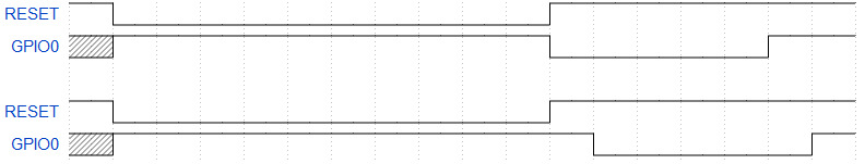
Now we know what is supposed to happen to trigger the bootloader, then how does the transistor circuit work? Instead of the assumption made in esptool.py, we have DTR controlling the base of a transistor whose collector is connected to RESET. We have RTS connected to the base of a transistor whose collector is connected to GPIO0. Remember, there is an external pullup resistor on RESET so default is HIGH.
When DTR is set HIGH and RTS is set LOW, this pulls RESET to LOW and GPIO0 is not controlled so it will eventually take its strapped value of HIGH. This has the same result as assuming DTR connects to GPIO0 and RTS to RESET. The processor is in the reset state.
When DTR is set LOW and RTS set HIGH, this disconnects RESET from the transistor and it gets pulled HIGH by the external pullup resistor. At the same time, GPIO0 is pulled to LOW by the transistor (with its internal pullup still engaged). This has the same result as assuming DTR connects to GPIO0 and RTS to RESET. The processor comes out of reset state and reads the GPIO0 value to be LOW to start the bootloader.
If you ask me why not just do DTR-GPIO0 and RTS-RESET, which has the same results, I don't know. Maybe they want to release control of the RESET and GPIO0 pins once they are done, by setting both DTR and RTS to HIGH. Then the reset button can pull RESET to LOW to reset without triggering the bootloader. You can also reclaim GPIO0 for other usage if you wise up on the requirements.
On adafruit's board, there is a 1uF cap between RESET and gnd so it will need some time to charge up (maybe for hardware debouncing the pin) and should kind of lag GPIO0's LOW.
So I guess in the end it all makes sense now.
Let me point out a few things I found:
According to WROOM doc, GPIO is a strapping pin and IIUC, there is an internal pullup/down that can be enabled by a register value. By default, it enables pullup register so after reset it will read HIGH (assuming no strong ext. pulldown) and the process (whichever process that is running) will read a HIGH on GPIO0 without the external transistor circuit thus will run the code.
According to the schematic diagram of the two transistors, it can be set low externally if RTS is HIGH and DTR is LOW. This probably starts the bootloading process.
I looked into esptool.py and found their pin toggle sequence starting from line 321:
Code: Select all
            self._port.setDTR(False)  # IO0=HIGH
            self._port.setRTS(True)   # EN=LOW, chip in reset
            time.sleep(0.1)
            if esp32r0_delay:
                # Some chips are more likely to trigger the esp32r0
                # watchdog reset silicon bug if they're held with EN=LOW
                # for a longer period
                time.sleep(1.2)
            self._port.setDTR(True)   # IO0=LOW
            self._port.setRTS(False)  # EN=HIGH, chip out of reset
            if esp32r0_delay:
                # Sleep longer after reset.
                # This workaround only works on revision 0 ESP32 chips,
                # it exploits a silicon bug spurious watchdog reset.
                time.sleep(0.4)  # allow watchdog reset to occur
            time.sleep(0.05)
            self._port.setDTR(False)  # IO0=HIGH, done
esptool.py line 314
Code: Select all
        # issue reset-to-bootloader:
        # RTS = either CH_PD/EN or nRESET (both active low = chip in reset
        # DTR = GPIO0 (active low = boot to flasher)
        #
        # DTR & RTS are active low signals,
        # ie True = pin @ 0V, False = pin @ VCC.
Now we know what is supposed to happen to trigger the bootloader, then how does the transistor circuit work? Instead of the assumption made in esptool.py, we have DTR controlling the base of a transistor whose collector is connected to RESET. We have RTS connected to the base of a transistor whose collector is connected to GPIO0. Remember, there is an external pullup resistor on RESET so default is HIGH.
When DTR is set HIGH and RTS is set LOW, this pulls RESET to LOW and GPIO0 is not controlled so it will eventually take its strapped value of HIGH. This has the same result as assuming DTR connects to GPIO0 and RTS to RESET. The processor is in the reset state.
When DTR is set LOW and RTS set HIGH, this disconnects RESET from the transistor and it gets pulled HIGH by the external pullup resistor. At the same time, GPIO0 is pulled to LOW by the transistor (with its internal pullup still engaged). This has the same result as assuming DTR connects to GPIO0 and RTS to RESET. The processor comes out of reset state and reads the GPIO0 value to be LOW to start the bootloader.
If you ask me why not just do DTR-GPIO0 and RTS-RESET, which has the same results, I don't know. Maybe they want to release control of the RESET and GPIO0 pins once they are done, by setting both DTR and RTS to HIGH. Then the reset button can pull RESET to LOW to reset without triggering the bootloader. You can also reclaim GPIO0 for other usage if you wise up on the requirements.
On adafruit's board, there is a 1uF cap between RESET and gnd so it will need some time to charge up (maybe for hardware debouncing the pin) and should kind of lag GPIO0's LOW.
So I guess in the end it all makes sense now.
Re: Trying to design an ESP32 dev board
It should be noted that with the transistors also RESET and GPIO0 are both High, when DTR and RTS are both low. That is the standard state for serial communication.
Re: Trying to design an ESP32 dev board
Yes, both pins are active LOW if the computer is ready to talk to the device. Arduino uses this default state (most boards use DTR) to drive RESET pin low for a short period, via a capacitor. When the capacitor is charged up, the MCU is brought out of reset and runs the bootloader.