Page 1 of 2
Working WS2812 LED Example
Posted: Fri Jun 06, 2014 10:34 am
by Markus Gritsch
Hi,
here is some MicroPython code which drives a WS2812 LED:
Code: Select all
# MicroPython example for controlling one WS2812 LED.
# Method similar to http://www.espruino.com/WS2811

from pyb import SPI

spi = SPI(1, SPI.MASTER, baudrate=6400000, polarity=0, phase=1)
spi.send(chr(0x00))

def byte2bits(byte):
    b0 = chr(0x03)
    b1 = chr(0x0F)
    bits = ''
    mask = 0x80
    while mask != 0:
        bits += b0 if ( byte & mask ) == 0 else b1
        mask >>= 1
    return bits

def sendColor(red, green, blue):
    spi.send(byte2bits(green)+byte2bits(red)+byte2bits(blue))

import math

n = 0
while True:
    r = int((1 + math.sin(n * 0.1324)) * 127)
    g = int((1 + math.sin(n * 0.1654)) * 127)
    b = int((1 + math.sin(n * 0.1)) * 127)
    sendColor(r, g, b)
    n += 1
    pyb.delay(20)

- 2014-06-06_12-10-59-554.png (63.23 KiB) Viewed 19260 times
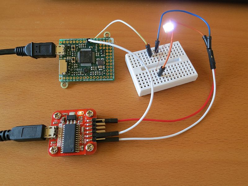
- IMG_5759_800x600_80.jpg (93.43 KiB) Viewed 19260 times
Have fun,
Markus
Re: Working WS2812 LED Example
Posted: Sun Jun 08, 2014 1:56 pm
by pfalcon
Markus Gritsch, great work and report on results! It only misses a video (heck, it's about
changing colors, I wanna see that!) to deserve an entry in
"Projects" forum. Well, just kidding - surely, it deserves to be there already, and please kindly consider postinf future posts like this there - that's where new users will look for expiration and ideas, and we don't want them to think there's lack of cool things to do with MicroPython, right? Thanks!
Re: Working WS2812 LED Example
Posted: Fri Jun 13, 2014 8:19 am
by fma
Hi Markus!
Thanks for sharing your code. I'm using it to drive a 11x11 leds matrix. For now, I only soldered 11 leds, and you code works fine (I didn't see the issue you reported
here, except when the SD card is enumarated/mounted, which is not really surprising).
Just to say that I'm very interested in any progress you can make on this project

Re: Working WS2812 LED Example
Posted: Fri Jun 13, 2014 10:58 am
by Markus Gritsch
The PCBs finally arrived and driving 10 LEDs works with an acceptable frame-rate:
http://youtu.be/GHmoE9ui4NU
Driving over hundred LEDs might be difficult with my approach, since it will get quite slow, and I am not sure if there is enough memory to hold the data string without any optimization.
Here is the updated code:
Code: Select all
# MicroPython example for controlling one WS2812 LED.
# Method similar to http://www.espruino.com/WS2811

from pyb import SPI

spi = SPI(1, SPI.MASTER, baudrate=6400000, polarity=0, phase=1)
spi.send(chr(0x00))

def byte2bits(byte):
    b0 = chr(0x03)
    b1 = chr(0x0F)
    bits = ''
    mask = 0x80
    while mask != 0:
        bits += b0 if ( byte & mask ) == 0 else b1
        mask >>= 1
    return bits

import math
import gc

buf = bytearray(10 * 3)
n = 0
while True:
    pos = 0
    while pos < len( buf ):
        red = int((1 + math.sin((n + pos) * 0.1324)) * 127)
        green = int((1 + math.sin((n + pos) * 0.1654)) * 127)
        blue = int((1 + math.sin((n + pos) * 0.1)) * 127)
        buf[pos] = green; buf[pos + 1] = red; buf[pos + 2] = blue
        pos += 3
    data = ''.join(list(map(byte2bits, buf)))
    pyb.disable_irq()
    spi.send(data)
    pyb.enable_irq()
    gc.collect()
    print(n)
    n += 1
Re: Working WS2812 LED Example
Posted: Fri Jun 13, 2014 11:12 am
by fma
Nice!
I tried to activate 121 leds, and I get a out of memory error

I also tried to use code emitters on byte2bits() function, but none of them work; I don't remember the errors. What can cause a problem, here?
Re: Working WS2812 LED Example
Posted: Sat Jun 14, 2014 8:01 pm
by Markus Gritsch
fma wrote:What can cause a problem, here?
Follow the directions pfalcon gave here:
http://forum.micropython.org/viewtopic. ... p=621#p621
Re: Working WS2812 LED Example
Posted: Sun Jun 15, 2014 1:18 pm
by randomhuman
Nice one, works well with Adafruit "Neopixels" as well, they use that same LED.
Re: Working WS2812 LED Example
Posted: Sun Jun 15, 2014 4:14 pm
by randomhuman
It is possible to run the SPI bus at half the baud rate, as the Espruino example was doing. This requires only four bits to be sent per actual bit of color data, which should help with the memory requirements. This might not be the best way to do it, but what I have looks like this:
Code: Select all
from pyb import SPI

spi = SPI(2, SPI.MASTER, baudrate=3200000, polarity=0, phase=1)
spi.send(chr(0x00))

def convert_byte_4(byte, zero_bits, one_bits):
    bits = bytearray(4)
    mask = 0x80
    for bit in range(0, 8, 2):
        bit1 = (zero_bits if (byte & (mask >> bit) == 0) else one_bits)
        bit2 = (zero_bits if (byte & (mask >> (bit + 1)) == 0) else one_bits)
        bits[bit//2] = bit1 << 4 | bit2
    return bits

def send_color(red, green, blue):
    ba = bytearray()
    for byte in (green, red, blue):
        converted = convert_byte_4(byte, 0x01, 0x3)
        for b in converted:
            ba.append(b)
    spi.send(ba)
Re: Working WS2812 LED Example
Posted: Mon Jul 07, 2014 2:47 pm
by Markus Gritsch
Just for completeness, here is the code without the big string concatenation. However, it still runs 2.5 times faster with the explicit call to gc.collect() in place.
Code: Select all
# MicroPython example for controlling one WS2812 LED.
# Method similar to http://www.espruino.com/WS2811

import pyb
from pyb import SPI

spi = SPI(1, SPI.MASTER, baudrate=6400000, polarity=0, phase=1)
spi.send(chr(0x00))

import math
import gc

led_count = 10
buf = bytearray(led_count * 3)
spi_data = bytearray(len(buf) * 8)

def buf2data():
    b0 = 0x03
    b1 = 0x0F
    i = 0
    size = len(spi_data)
    while i < size:
        byte = buf[ i >> 3 ]
        mask = 0x80
        while mask != 0:
            spi_data[ i ] = b0 if ( byte & mask ) == 0 else b1
            mask >>= 1
            i += 1

def send_buf():
    buf2data()
    pyb.disable_irq()
    spi.send(spi_data)
    pyb.enable_irq()
    gc.collect()

n = 0

def step():
    global n
    pos = 0
    while pos < len( buf ):
        shift = 0
        red = int((1 + math.sin((n + pos) * 0.1324)) * 127) >> shift
        green = int((1 + math.sin((n + pos) * 0.1654)) * 127) >> shift
        blue = int((1 + math.sin((n + pos) * 0.1)) * 127) >> shift
        buf[pos] = green; buf[pos + 1] = red; buf[pos + 2] = blue
        pos += 3
    send_buf()
    print(n)
    n += 1

def loop():
    while True:
        step()
        pyb.delay(10)

loop()
Re: Working WS2812 LED Example
Posted: Mon Jul 07, 2014 10:25 pm
by kfricke
Slight modification makes a rudimentary clock on a led ring. The time is off by a bunch of units, but works like a charm. I do use one of
those 12x LED rings.
Code: Select all
# MicroPython example for controlling one WS2812 LED.
# Method similar to http://www.espruino.com/WS2811

import pyb
from pyb import SPI

spi = SPI(1, SPI.MASTER, baudrate=6400000, polarity=0, phase=1)
spi.send(chr(0x00))

import math
import gc

led_count = 12
buf = bytearray(led_count * 3)
spi_data = bytearray(len(buf) * 8)

def buf2data():
    b0 = 0x03
    b1 = 0x0F
    i = 0
    size = len(spi_data)
    while i < size:
        byte = buf[ i >> 3 ]
        mask = 0x80
        while mask != 0:
            spi_data[ i ] = b0 if ( byte & mask ) == 0 else b1
            mask >>= 1
            i += 1

def send_buf():
    buf2data()
    pyb.disable_irq()
    spi.send(spi_data)
    pyb.enable_irq()
    gc.collect()

rtc = pyb.RTC()

def step():
    global rtc

    dt = rtc.datetime()
    hour = dt[4]
    minute = dt[5]
    second = dt[6]
    print(hour, minute, second)

    pos = 0
    for i in range(0, len(buf)):
        buf[i] = 0

    buf[int(hour / 2) * 3 + 1] = 8
    buf[int(minute / 5) * 3 + 2] = 8
    buf[int(second / 5) * 3] = (second % 2) * 16

    send_buf()

def loop():
    while True:
        step()
        pyb.delay(500)

loop()