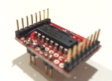
This afternoons work; inline assembler tutorial and lots of googe'ling ... but no PWM speed control, yet ...

Code: Select all
import pwm
pY3 = pwm.PWM(pyb.Pin.board.Y3) #pass in desired pin, only Y3,Y4,Y7,Y8,Y9,Y10,X1,X2,X3,X4,X9,X10 known to work
pY3.duty(125) #range is 0 (off - 0v) to 255 (on - 3.3v)
pY3.duty()
125                #current set duty is returned
Code: Select all
import pyb, stm

#as pwm is configured 0-3.3v is 0-10000
# used to truncate to 0-255;
# change if you need finer resolution
RESOLUTION = 255

#for each pin name
# list of possible pwm available alt fn's
# and corresponding timer/channel
__PIN_TIMERS  = { \
  'A0':   { 0b0010: ( 5,1) }, \
  'A1':   { 0b0001: ( 2,2), 0b0010: ( 5,2) }, \
  'A2':   { 0b0001: ( 2,3), 0b0010: ( 5,3), 0b0011: ( 9,1) }, \
  'A3':   { 0b0001: ( 2,4), 0b0010: ( 5,4), 0b0011: ( 9,2) }, \
  'A6':   { 0b0010: ( 3,1), 0b1001: (13,1) }, \
  'A7':   { 0b0010: ( 3,2), 0b1001: (14,1) }, \
  'A8':   { 0b0001: ( 1,1) }, \
  'A9':   { 0b0001: ( 1,2) }, \
  'A10':  { 0b0001: ( 1,3) }, \
  'A11':  { 0b0001: ( 1,4) }, \
  'B0':   { 0b0010: ( 3,3) }, \
  'B1':   { 0b0010: ( 3,4) }, \
  'B3':   { 0b0001: ( 2,2) }, \
  'B4':   { 0b0010: ( 3,1) }, \
  'B5':   { 0b0010: ( 3,2) }, \
  'B6':   { 0b0010: ( 4,1) }, \
  'B7':   { 0b0010: ( 4,2) }, \
  'B8':   { 0b0010: ( 4,3), 0b0011: (10,1) }, \
  'B9':   { 0b0010: ( 4,4), 0b0011: (11,1) }, \
  'B10':  { 0b0001: ( 2,3) }, \
  'B11':  { 0b0001: ( 2,4) }, \
  'B14':  { 0b1001: (12,1) }, \
  'B15':  { 0b1001: (12,2) }, \
  'C6':   { 0b0010: ( 3,1), 0b0011: ( 8,1) }, \
  'C7':   { 0b0010: ( 3,2), 0b0011: ( 8,2) }, \
  'C8':   { 0b0010: ( 3,3), 0b0011: ( 8,3) }, \
  'C9':   { 0b0010: ( 3,4), 0b0011: ( 8,4) }, \
  'D12':  { 0b0010: ( 4,1) }, \
  'D13':  { 0b0010: ( 4,2) }, \
  'D14':  { 0b0010: ( 4,3) }, \
  'D15':  { 0b0010: ( 4,4) }, \
  'E5':   { 0b0011: ( 9,1) }, \
  'E6':   { 0b0011: ( 9,2) }, \
  'E9':   { 0b0001: ( 1,1) }, \
  'E11':  { 0b0001: ( 1,2) }, \
  'E13':  { 0b0001: ( 1,3) }, \
  'E14':  { 0b0001: ( 1,4) }, \
  'F6':   { 0b0011: (10,1) }, \
  'F7':   { 0b0011: (11,1) }, \
  'F8':   { 0b1001: (13,1) }, \
  'F9':   { 0b1001: (14,1) }, \
  'H9':   { 0b1001: (12,2) }, \
  'H10':  { 0b0010: ( 5,1) }, \
  'H11':  { 0b0010: ( 5,2) }, \
  'H12':  { 0b0010: ( 5,3) }, \
  'H6':   { 0b1001: (12,1) }, \
  'I0':   { 0b0010: ( 5,4) }, \
  'I2':   { 0b0011: ( 8,4) } \
  }

class PWM:
  """dirty Pulse Width Modulation class"""

  def __init__(self, pin, afmode=None):
    if not pin.name() in __PIN_TIMERS:
      raise ValueError('Pin does not support pwm')
    if afmode == None:
      #select the first timer in the dictionary
      pwm_afmode = list(__PIN_TIMERS[pin.name()].keys())[0]
    else:
      pwm_afmode = afmode
    if not pwm_afmode in __PIN_TIMERS[pin.name()]:
      raise ValueError('Pin does not support afmode {0}'.format(bin(afmode)))
    self.pin      = pin
    self.gpio     = eval('stm.GPIO{0}'.format(pin.name()[0]))
    pwm_pin       = int(self.pin.name()[1:])
    pwm_timer_no  = __PIN_TIMERS[self.pin.name()][pwm_afmode][0]
    pwm_timer_ch  = __PIN_TIMERS[self.pin.name()][pwm_afmode][1]

    #setup gpio
    #set alternate fn mode, before setting pin to alternate function
    if pwm_pin < 7:
      stm.mem32[self.gpio + stm.GPIO_AFR0]   |= pwm_afmode << (pwm_pin * 4)
    elif pwm_pin == 7:
      #avoid potential overflow on 32nd bit being set
      stm.mem8[self.gpio + stm.GPIO_AFR0 + 3]   |= pwm_afmode << 4
    elif pwm_pin < 15:
      stm.mem32[self.gpio + stm.GPIO_AFR1]   |= pwm_afmode << ((pwm_pin - 8) * 4)
    elif pwm_pin == 15:
      #avoid potential overflow on 32nd bit being set
      stm.mem8[self.gpio + stm.GPIO_AFR1 + 3]   |= pwm_afmode << 4

    if pwm_pin < 15:
      stm.mem32[self.gpio + stm.GPIO_MODER]       |= 0b10 << (pwm_pin * 2)
      stm.mem32[self.gpio + stm.GPIO_OSPEEDR]     |= 0b10 << (pwm_pin * 2)
    elif pwm_pin == 15:
      stm.mem8[self.gpio + stm.GPIO_MODER + 3]    |= 0b10 << 6
      stm.mem8[self.gpio + stm.GPIO_OSPEEDR + 3]  |= 0b10 << 6

    #setup timer
    #TODO: work out how to init timer directly, so can use reserved ones TIM3
    pyb.Timer(pwm_timer_no).init(freq=5)    #use pyb module to kickstart the timer
    pwm_timer                               =  eval('stm.TIM{0}'.format(pwm_timer_no))
    self.__pwm_duty                         =  pwm_timer + eval('stm.TIM_CCR{0}'.format(pwm_timer_ch))
    stm.mem32[self.__pwm_duty]              =  0       #make sure duty is 0
    stm.mem32[pwm_timer + stm.TIM_ARR]      =  9999    #replicate damiens's prescalar, period
    stm.mem32[pwm_timer + stm.TIM_PSC]      =  83      #gives 10,000 steps between 0 and 3.3v
    stm.mem32[pwm_timer + stm.TIM_DIER]     |= 0b1
    stm.mem32[pwm_timer + stm.TIM_SR]       |= 0b11110 #sets all channel interupt flags
    if pwm_timer_ch <= 2:
      stm.mem32[pwm_timer + stm.TIM_CCMR1]  |= 0b01101000 << ((pwm_timer_ch - 1) * 8)
    else:
      stm.mem32[pwm_timer + stm.TIM_CCMR2]  |= 0b01101000 << ((pwm_timer_ch - 3) * 8)
    stm.mem32[pwm_timer + stm.TIM_CCER]     |= 0b1 << ((pwm_timer_ch -1) * 4)
    stm.mem32[pwm_timer + stm.TIM_DMAR]     |= 0b1

  def duty(self, value=None):
    if value == None:
      return int( stm.mem32[self.__pwm_duty] / 10000 * RESOLUTION )
    else:
      if value > RESOLUTION: value = RESOLUTION
      if value < 0:   value = 0
      stm.mem32[self.__pwm_duty] = int(value / RESOLUTION * 10000)