Electrical network analyser/signal generator

Showroom for MicroPython related hardware projects.
Target audience: Users wanting to show off their project!
User avatar
pythoncoder
Posts: 5956
Joined: Fri Jul 18, 2014 8:01 am
Location: UK
Contact:

Electrical network analyser/signal generator

Post by pythoncoder » Wed Dec 13, 2017 6:51 pm

This uses a Pyboard driving a 4.3inch TFT display with touchscreen controller. It currently has two modes, a signal generator capable of producing sine, pulse, sawtooth, triangle and random noise and an electrical network analyser which can produce Bode and Nyquist plots of arbitrary linear networks. It is based on a simple analog PCB which amplifies and level-shifts a Pyboard DAC to produce an output of up to +-3.3V and capable of driving loads as low as 8Ω. The input circuit has a 1MΩ input impedance and level shifts voltages in that range to match the Pyboard ADC. DC coupling is used throughout. It includes a programmable gain amplifier to extend the dynamic range of the Pyboard ADC. The display hardware uses the PCB of @Robert-hh together with his display driver code and my touch GUI interface.
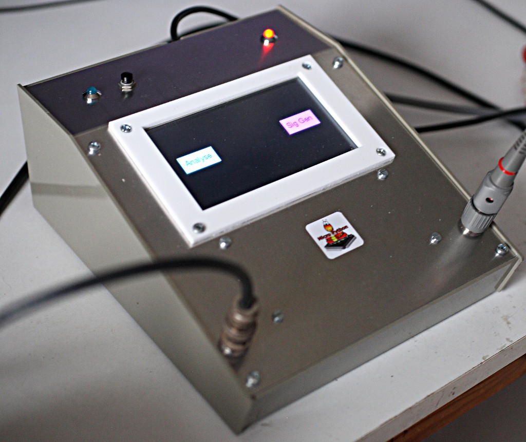
This image shows the starting instrument selection screen.
Image
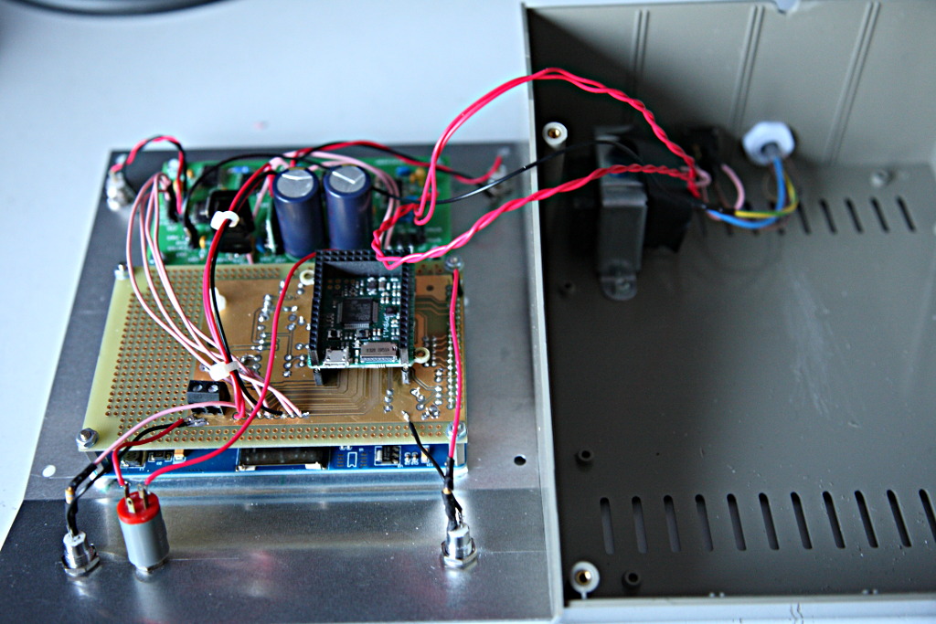
Internal construction:
Image
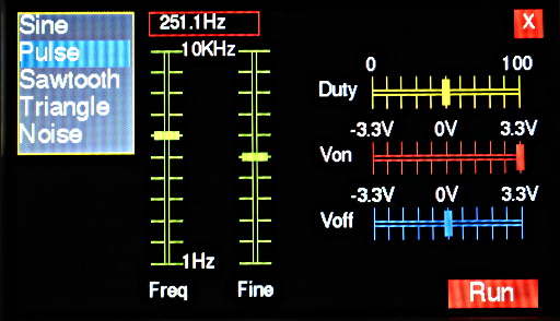
This is the control panel for the signal generator. The coarse and fine frequency controls enable precise frequency selection over a 1Hz-10KHz range.
Image
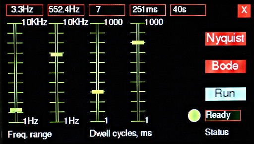
And this for the network analyser. This works using a stepwise-swept sine wave generator. The "dwell" controls determine the duration of running at each frequency point in terms of time and cycles: a delay before reading provides high-Q circuits with time to stabilise.
Image
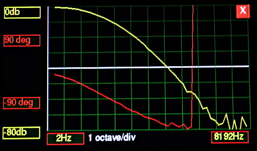
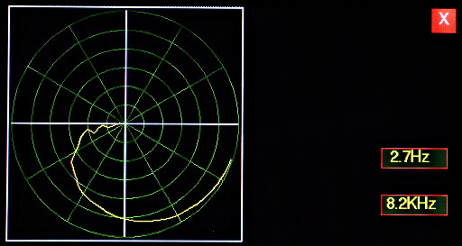
Here are some samples. Firstly a classic second order passive low-pass filter. Bode and Nyquist:
Image

Image
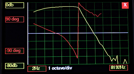
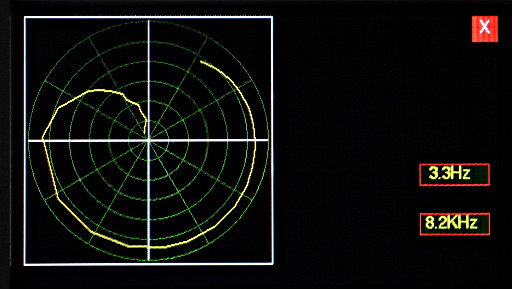
A third-order Sallen-Key low-pass filter with 100Hz cutoff cascaded with a first-order passive high pass filter:
Image

Image
Lastly, for comedy value, I tried an audio test. Bear in mind that the speaker was not a particularly good one, the microphone was an ancient Grundig of unknown quality, the mic preamp was lashed up on a breadboard and the test was done indoors in a small resonant room. Exactly how not to do these things...
Image
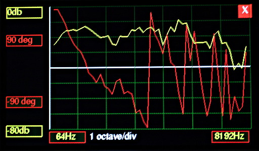
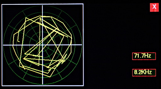
The wild phase changes are of course due to the time delay between the speaker and the mic: what's really needed is a means of displaying the departure from linear phase. For an even greater comedy effect here is the Nyquist plot. This shows the limitation of my instrument in that there are only 50 (logarithmic) frequency steps, so a nice neat spiral it is not!
Image
For anyone still following there were two significant challenges. The first is getting phase measurements from the Pyboard, which does not currently support the more advanced ADC modes of the chip. I use DAC continuous mode to generate the sinewave, feeding it back into an ADC. I then detect a positive going transition and start an ADC timed read of the input signal. Some phase compensation is applied to try to offset errors caused (presumably) by a time delay in initiating the read. Phase is determined by correlating the input sample set with calculated sine and cosine values. In practice phase measurements lose accuracy above about 5KHz and below about -50dB amplitude, and I stop trying to perform the measurement outside certain thresholds of amplitude and frequency. I believe this performance could be improved with better linear circuit design and construction, more noise-immune phase detection algorithms and/or firmware supporting the dual ADC modes.

The second challenge resulted from the design of the display hardware which uses the two Pyboard DAC pins as part of a fast 8-bit digital port. Re-configuring this would affect Robert Hammelrath's driver and would require a new design of PCB. So I dynamically re-configure the pin as an analog output and suspend display operation while the instrument is producing output. This is less disruptive than you might think.
Peter Hinch
Index to my micropython libraries.

User avatar
Roberthh
Posts: 3667
Joined: Sat May 09, 2015 4:13 pm
Location: Rhineland, Europe

Re: Electrical network analyser/signal generator

Post by Roberthh » Thu Dec 14, 2017 7:25 am

This is a really impressive project, covering do mamny areas, eletronic design, software, theoretical background and not least a fine mechanical assembly. It also shows the power of this little pyboard and MicroPython for non-trivial tasks.
And, b.t.w., it is a proof that indeed old dogs CAN learn new tricks.

User avatar
kfricke
Posts: 342
Joined: Mon May 05, 2014 9:13 am
Location: Germany

Re: Electrical network analyser/signal generator

Post by kfricke » Thu Dec 14, 2017 7:54 am

All I can say is „Wow!“

User avatar
pythoncoder
Posts: 5956
Joined: Fri Jul 18, 2014 8:01 am
Location: UK
Contact:

Re: Electrical network analyser/signal generator

Post by pythoncoder » Thu Dec 14, 2017 9:46 am

Thank you both :D

A couple of design detail I didn't mention. It is intended to be extensible to support further possible instruments. When you exit from the analyser or signal generator a hard reset is issued, causing the initial instrument selection screen to appear. Each instrument is a separate Python module so each gets the maximum possible amount of free RAM. Since all code is frozen bytecode this reboot is almost instantaneous with the screen blanking for a fraction of a second. I find the reboot speed rather impressive.

The input circuit has no anti-aliasing filter. This is because the network analyser produces a sinewave. The network under test is presumed to be linear, hence the input circuit theoretically sees only that frequency. It is always sampled at N times the rate so aliasing of the signal should not occur. However in practice there is significant digital noise which can be aliased. Designing a variable cutoff AA filter to cover the range 1Hz to 10KHz would be, er, interesting. However an improved input circuit would include a fixed cutoff lowpass filter to reject high frequency digital noise, with a matching filter in line with the DAC output monitor to maintain transition timing accuracy.

While I can see a number of ways that dynamic range and phase accuracy could be improved it works well enough and I doubt I'll redesign the linear board.

A few links related to the display subsystem:
The GUI code https://github.com/peterhinch/micropython-tft-gui.git
Robert Hammelrath's original drivers
https://github.com/robert-hh/XPT2046-to ... yBoard.git
https://github.com/robert-hh/SSD1963-TF ... or-PyBoard
My fork of the TFT library (used by the GUI)
https://github.com/peterhinch/SSD1963-T ... yBoard.git
Peter Hinch
Index to my micropython libraries.

User avatar
roland_vs
Posts: 89
Joined: Tue Dec 08, 2015 8:28 pm
Location: Netherlands
Contact:

Re: Electrical network analyser/signal generator

Post by roland_vs » Thu Dec 14, 2017 10:40 am

@pythoncoder You never cease to amaze me!

I'm busy using the AD8302 as a frontend together with a STM32L476 (with MPY) for some RF measurements beyond the 20kHz :-)
But as always your example is inspiring!!!

Roland

SpotlightKid
Posts: 463
Joined: Wed Apr 08, 2015 5:19 am

Re: Electrical network analyser/signal generator

Post by SpotlightKid » Thu Dec 14, 2017 3:15 pm

Looks very nice!

Did you machine the enclosure lid yourself?

User avatar
pythoncoder
Posts: 5956
Joined: Fri Jul 18, 2014 8:01 am
Location: UK
Contact:

Re: Electrical network analyser/signal generator

Post by pythoncoder » Fri Dec 15, 2017 6:36 am

@SpotlightKid I did everything with hand tools apart from the acrylic display bezel which I drew in Inkscape and had laser-cut.
Peter Hinch
Index to my micropython libraries.

jeffm
Posts: 23
Joined: Tue Mar 10, 2015 9:11 am

Re: Electrical network analyser/signal generator

Post by jeffm » Sat Dec 16, 2017 8:08 am

A really impressive project.
Could you implement a simple oscilloscope mode with the same hardware?

User avatar
pythoncoder
Posts: 5956
Joined: Fri Jul 18, 2014 8:01 am
Location: UK
Contact:

Re: Electrical network analyser/signal generator

Post by pythoncoder » Sat Dec 16, 2017 9:18 am

This project viewtopic.php?f=5&t=3990 has an oscilloscope display but it isn't real time.

The difficulty would be implementing concurrent fast real time data capture and display. The ADC read_timed method is a blocking method, so this project and the one referenced above work by capturing a buffer full of samples and then displaying the outcome.

I think a true oscilloscope display would require modifying the firmware to use DMA so that a buffer could be constantly updated as a background task. However I'm talking off the top of my head here, I haven't thought this through in detail ;)

Enhancing the Pyboard's ADC modes is something I've long considered attempting, but I'm not sure I have the necessary know-how.
Peter Hinch
Index to my micropython libraries.

User avatar
pythoncoder
Posts: 5956
Joined: Fri Jul 18, 2014 8:01 am
Location: UK
Contact:

Oscilloscope?

Post by pythoncoder » Mon Dec 18, 2017 7:22 am

@jeffm On further thought I think you could go some way towards an oscilloscope by using ADC timed read for the faster timebase speeds and an ADC read run as a timer callback for the slower ones. But there's an awful lot of realtime display updating to do.

To build a general purpose 'scope there would be quite a few practical issues with the linear circuitry. You'd need an anti-alias filter with a widely variable cutoff frequency. You'd need a variable gain input amplifier with a much wider range than the one in my instrument. Unless, of course, the 'scope was for a special purpose to display a particular signal with fairly predictable frequency and amplitude, when it might be practical.

Not a route I plan to go down - my 'scope is a good deal batter than anything likely to be achievable this way.
Peter Hinch
Index to my micropython libraries.

Post Reply