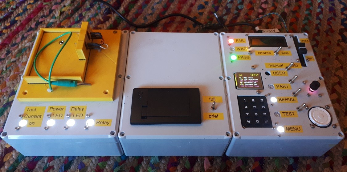
I'ts Automated Test Equipment (ATE) for use by our production department to test Non-Intrusive Current (NIC) sensors. Their existing test equipment is cumbersome, mandraulic and prone to (occasional) errors in record keeping and record preservation.
My magic ATE-NIC reduces unit test time from 2 ~ 3 minutes to under 20 sec and is paperless.
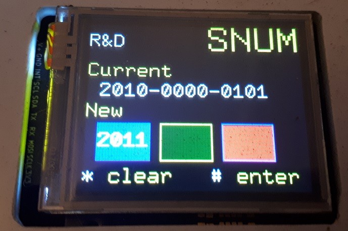
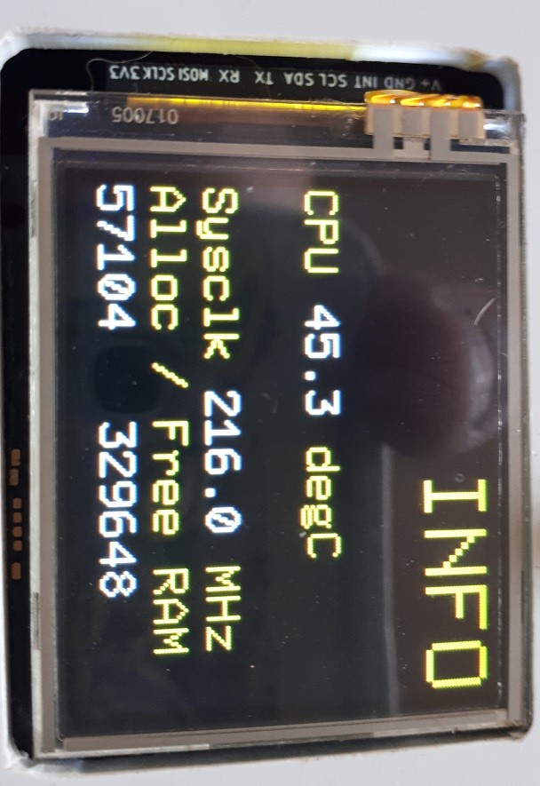
Unit under test is placed in bed of nails (LHS) and test current loop inserted. Serial number is entered on the keypad and (TEST) is pressed. Presto. Lots of white status lights flicker ... culminating with a solid green (PASS) or solid (RED) LED. The user needs to press the GREEN/RED LED button to 'accept' the result. Test Report incl. ATE health, date timestamp, test measurements, userID etc is saved to a .TXT file. These test results are, as needed uploaded to network via USB.
Future enhancements are to (a) print packing slip using central thermal printer, (b) support self-calibration, (c) add barcode scanner to auto-capture partNo & serialNo, (d) RFID detector to register UserID. The barcode scanner will reduce total unit test time to under 5 sec.
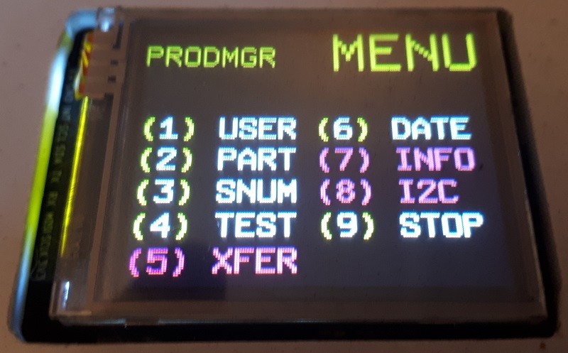
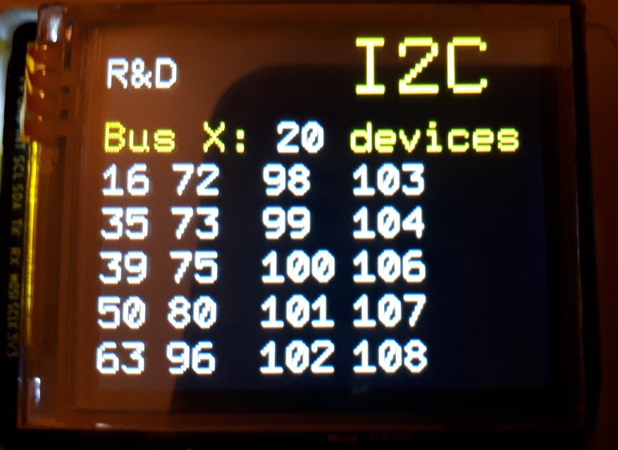
Here the options available to the user is context sensitive w.r.t. user access permissions, e.g. Production, Production Manager, R&D, Guest.
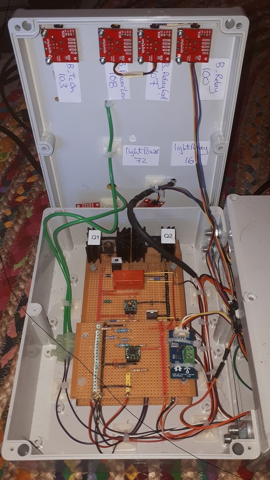
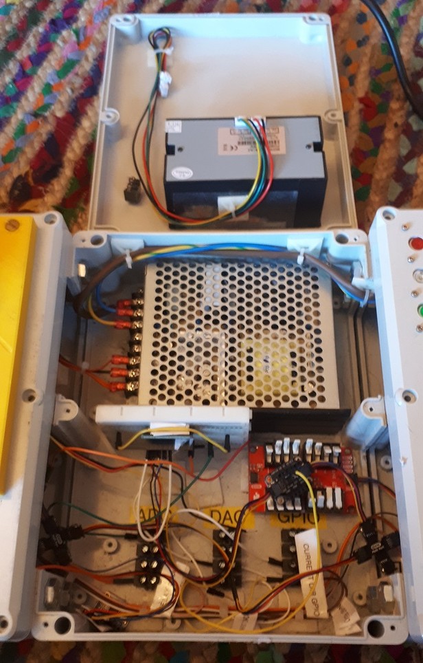
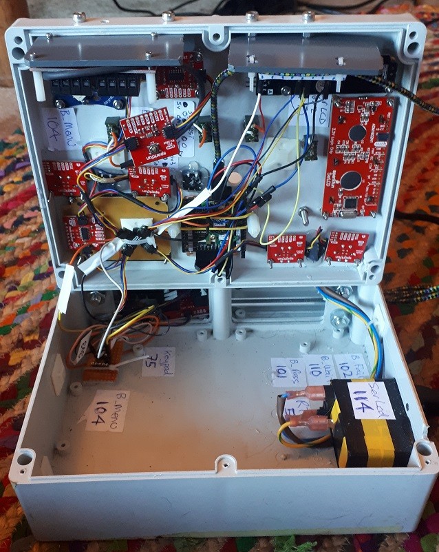
Next posting I'll show the innnards.