
@pythoncoder
Thanks a lot for explanation "DNF", aah "do not fit". Until yet I did it not understood...
Aah: There are the five pads on rear side, I thought it would be test points.
No, it is do not fit U4...
Help with hooking up a 5V logic converter
Re: Help with hooking up a 5V logic converter
As said, I am a total noob, and even more confused after this whole discussion here.
You are using some terminology that don't correspond to the official names of the PIN layout.
Could someone be so kind, to dumb it down for me, which PINS here:
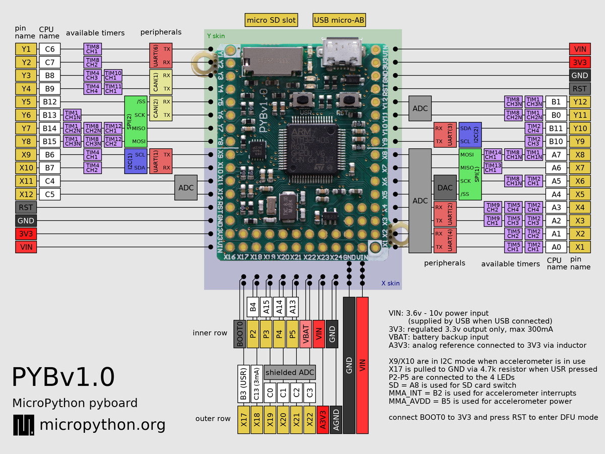
[img]http://micropython.org/resources/pybv10-pinout.jpg[/img]
should be connected to here:
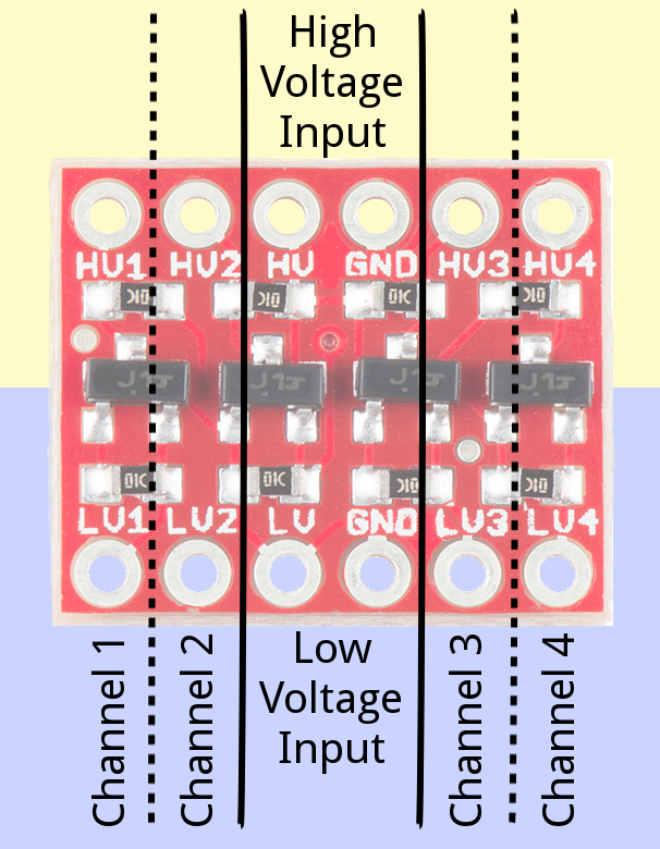
[img]https://cdn.sparkfun.com/assets/f/d/5/8 ... 8b456b.png[/img]
If in the end its not exactly 5V thats coming out, thats not such a big deal for me.
You are using some terminology that don't correspond to the official names of the PIN layout.
Could someone be so kind, to dumb it down for me, which PINS here:
[img]http://micropython.org/resources/pybv10-pinout.jpg[/img]
should be connected to here:
[img]https://cdn.sparkfun.com/assets/f/d/5/8 ... 8b456b.png[/img]
If in the end its not exactly 5V thats coming out, thats not such a big deal for me.
Re: Help with hooking up a 5V logic converter
@felixsc
Normally you should not need a level converter.
See circuit schematic of pyboard, USB-Port!
It's a good idea to insert also 560 Ohms for other I/O.
For digital Outputs, the 3V3 are high enough (typ min 2.4V).
For digital Inputs the STM32F4 is 5V tolerant.
If you want use the sparkfun level converter, connect the HV
to V+ from Pyboard and LV to 3V3.
Supplying via USB, V+ will be about 4V
If you want HV exactly 5V you must use an extern power supply for it.
By the way: ADAFRUIT ID2190 ($9.95) is a fantastic product for
supplying all such 5V cases, from input 3..12V! (boost AND buck!)
Re: Help with hooking up a 5V logic converter
There were two reasons for the power supply changes on PYBv1.1. The first was to reduce quiescent current and the second was to allow a Lion/Lipo battery to be connected to Vbat while USB is connected. Mosfet Q1 provides a low voltage drop path for battery power but disconnects the battery whenever USB is plugged in to prevent overcharging the battery from 5V.
The reason D1 is silicon is that Schottky diode leakage current, especially at high temperatures, can develop enough voltage drop across R22 to turn the Mosfet off when running on battery and cause V+ to droop due to the Q1 body diode drop.
The reason D1 is silicon is that Schottky diode leakage current, especially at high temperatures, can develop enough voltage drop across R22 to turn the Mosfet off when running on battery and cause V+ to droop due to the Q1 body diode drop.
Re: Help with hooking up a 5V logic converter
Another way to get 5V outputs is to program the pins as Open Drain and add pull-up resistors to 5V. This has some impact on power consumption. Fast signals need lower value resistors, typically 330R to 1k.
You can also drive 4V blue LEDs from 5V using Open Drain outputs.
Most STM32 inputs are 5V tolerant and don't need level translators. Note that the DAC pins PA4 and PA5 are not 5V tolerant on pyboard or any STM32. STM32L4xx have other non 5V tolerant pins as well. Always check the data sheet for the specific MCU.
Re: Help with hooking up a 5V logic converter
How about this adafruit miniboost: https://www.adafruit.com/product/3661Wolfgang wrote: ↑Thu Jan 04, 2018 11:22 am@felixsc
Normally you should not need a level converter.
See circuit schematic of pyboard, USB-Port!
It's a good idea to insert also 560 Ohms for other I/O.
For digital Outputs, the 3V3 are high enough (typ min 2.4V).
For digital Inputs the STM32F4 is 5V tolerant.
If you want use the sparkfun level converter, connect the HV
to V+ from Pyboard and LV to 3V3.
Supplying via USB, V+ will be about 4V
If you want HV exactly 5V you must use an extern power supply for it.
By the way: ADAFRUIT ID2190 ($9.95) is a fantastic product for
supplying all such 5V cases, from input 3..12V! (boost AND buck!)
This seems to not even require an additional battery.

Re: Help with hooking up a 5V logic converter
Depending on you application, the current delivered by this board could be too low. I personally prefer regulators from Pololu, like the s7v8a, which is adjustable to the desired output voltage, or the fixed current variants of it, like S7V8F5. Small size (~ TO220 package), enable input, low standby.
But I do not unterstand your remark: "This seems to not even require an additional battery."
None of these require an additional battery, only the main one.
But I do not unterstand your remark: "This seems to not even require an additional battery."
None of these require an additional battery, only the main one.
Re: Help with hooking up a 5V logic converter
@felixsc
For loads under about 10mA (continuous max) the miniboost can be a good solution.
Charge Pump Converters have some problems. They can not really regulate, producing much noise on both sides, too much noise for ADC/DAC onboard and the efficiency is very bad. With 3V Input 50%, with 4V Input 30-40%. This means: For 10mA load the input current is four times higher. If you supply it with 3V3 from pyboard, peak loadings with more than 50mA will shutdown the system!
The question is, for what you need the 5V. For more help we need more information from you, like a schematic including the peripherals and description about the function of the application!
Re: Help with hooking up a 5V logic converter
The application is to very simply provide a 5V TTL output, there should be virtually no current drain. And noise in the amplitude is quite irrelevant for this purpose, can be higher than 5V as long as its high enough to trigger the device.Wolfgang wrote: ↑Fri Jan 05, 2018 11:33 am@felixsc
For loads under about 10mA (continuous max) the miniboost can be a good solution.
Charge Pump Converters have some problems. They can not really regulate, producing much noise on both sides, too much noise for ADC/DAC onboard and the efficiency is very bad. With 3V Input 50%, with 4V Input 30-40%. This means: For 10mA load the input current is four times higher. If you supply it with 3V3 from pyboard, peak loadings with more than 50mA will shutdown the system!
The question is, for what you need the 5V. For more help we need more information from you, like a schematic including the peripherals and description about the function of the application!
-
pythoncoder

- Posts: 5956
- Joined: Fri Jul 18, 2014 8:01 am
- Location: UK
- Contact:
Re: Help with hooking up a 5V logic converter
Most devices with a TTL input can happily be driven by a 0 to 3.3V signal.
Peter Hinch
Index to my micropython libraries.
Index to my micropython libraries.