
Hey Guys,
I hooked up four SCT-013 (-030 / 30A) with a CD4051BE to the ESP8266 (NodeMCU). The CD4051BE is only to expand the amount of analogue interfaces. I hooked it up to the 4 groups in my fusebox but I think I'm getting crap readings. Anyone any idea? You can find the values here: https://thingspeak.com/channels/175100
SCT-013 values
SCT-013 values
NodeMCU v0.9 / V1 / V2 / V3
WeMos D1 Mini
WeMos Lolin32 v1.0.0
WeMos Lolin D32 Pro V2
WeMos D1 Mini
WeMos Lolin32 v1.0.0
WeMos Lolin D32 Pro V2
Re: SCT-013 values
It depends what you're measuring there. If this is a fuse box for something 240VAC (like a house) which has negligible actual load at the moment then pseudo-random 0.4A fluctuations are to be expected just as general noise in the system. Whether anything can be inferred between the graphs depends on whether you are plotting circuits or phases.patvdleer wrote:Hey Guys,
I hooked up four SCT-013 (-030 / 30A) with a CD4051BE to the ESP8266 (NodeMCU). The CD4051BE is only to expand the amount of analogue interfaces. I hooked it up to the 4 groups in my fusebox but I think I'm getting crap readings. Anyone any idea? You can find the values here: https://thingspeak.com/channels/175100
Re: SCT-013 values
It is indeed 230/240V AC but since my electric bill is quite high and I don't know why so I thought I would measure it. Since I'm not sure wetter to place it over the blue, brown or both I tried all but same difference in the readings.
NodeMCU v0.9 / V1 / V2 / V3
WeMos D1 Mini
WeMos Lolin32 v1.0.0
WeMos Lolin D32 Pro V2
WeMos D1 Mini
WeMos Lolin32 v1.0.0
WeMos Lolin D32 Pro V2
Re: SCT-013 values
You clip the CT around the "live" conductor. That should be the brown one in your case (colours vary by both country and era of installation). Since this is a domestic installation I'm assuming it is single phase and you're attempting to plot multiple circuits (i.e. independent fuses for floors, lights, sockets etc).patvdleer wrote:It is indeed 230/240V AC but since my electric bill is quite high and I don't know why so I thought I would measure it. Since I'm not sure wetter to place it over the blue, brown or both I tried all but same difference in the readings.
If you're reading the same no matter what wire you use (and presumably no matter what you turn on or off in the house) then you're just reading noise.
Try simplifying. Attach one CT to an identified circuit (say ground floor sockets) and then apply a known additional load. A standard kettle draws about 7-8A. A typical fan heater is about the same (the rating will be printed on the device somewhere).

Re: SCT-013 values
I'm asking myself how that can work. As far as I can read, SCT-013 is a simple transformer, which delivers into a load an AC current proportional to the field it captures. To get a reasonable result out of that, which you can measure with an ESP8266, you have to convert that into a DC voltage, by precision rectifying and smoothing. Did you use such a circuitry?
If not, at least the CD4051BE prevents the ESP8266 from being killed.
If not, at least the CD4051BE prevents the ESP8266 from being killed.
Re: SCT-013 values
SCT-013 is a 2000 turn split core CT with 100A range so for 5V logic you can reasonable results with a 33 ohm burden resistor (24 ohm for 3V3 logic) and a voltage divider. Far better to use something like a CS5480 though.Roberthh wrote:I'm asking myself how that can work. As far as I can read, SCT-013 is a simple transformer, which delivers into a load an AC current proportional to the field it captures. To get a reasonable result out of that, which you can measure with an ESP8266, you have to convert that into a DC voltage, by precision rectifying and smoothing. Did you use such a circuitry?
If not, at least the CD4051BE prevents the ESP8266 from being killed.
Re: SCT-013 values
I understand the principle. If I look up the examples n the net, you'll get a sinusoidal signal, which has to be appropriately captured. And that was my thought, if that is don in the software.
-
pythoncoder

- Posts: 5956
- Joined: Fri Jul 18, 2014 8:01 am
- Location: UK
- Contact:
Re: SCT-013 values
And DC biassing is required to put the zero point in the middle of the ADC range. The range is 0-1V on the ESP8266. So it needs biassing to 0.5V and the burden resistor altering proportionally.
Looking at the burden resistor calculations 100A RMS will produce a secondary current of 50mA RMS. A burden resistor of 33 ohms will yield 1.65V RMS or 4.67V PP. So the web reference is based on 100A RMS full scale. For the same range on an ESP8266 you'd want 6.6 ohms, however 100A RMS is 23KW on a 230V circuit. You may want a higher value for a more realistic full scale range.
As @Roberthh says, you'll then need code to effectively rectify and average the incoming values. This still assumes a resistive load on the mains circuit. To really do the job properly you need a second ADC and a means of reading the voltage, with a software phase sensitive detector to yield the in phase current (which is what your meter reads, and what you are charged for).
Peter Hinch
Index to my micropython libraries.
Index to my micropython libraries.
Re: SCT-013 values
So far no luck, I'll try it the coming weekend with a stick welder.Lysenko wrote:You clip the CT around the "live" conductor. That should be the brown one in your case (colours vary by both country and era of installation). Since this is a domestic installation I'm assuming it is single phase and you're attempting to plot multiple circuits (i.e. independent fuses for floors, lights, sockets etc).patvdleer wrote:It is indeed 230/240V AC but since my electric bill is quite high and I don't know why so I thought I would measure it. Since I'm not sure wetter to place it over the blue, brown or both I tried all but same difference in the readings.
If you're reading the same no matter what wire you use (and presumably no matter what you turn on or off in the house) then you're just reading noise.
Try simplifying. Attach one CT to an identified circuit (say ground floor sockets) and then apply a known additional load. A standard kettle draws about 7-8A. A typical fan heater is about the same (the rating will be printed on the device somewhere).
NodeMCU v0.9 / V1 / V2 / V3
WeMos D1 Mini
WeMos Lolin32 v1.0.0
WeMos Lolin D32 Pro V2
WeMos D1 Mini
WeMos Lolin32 v1.0.0
WeMos Lolin D32 Pro V2
Re: SCT-013 values
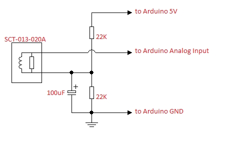
I'm using the SCT-013-030 which should have a 62 ohm build-in and is 1800:1 ratio based on http://webmeteobox.ru/docs/SCT013-030V.pdf
I made my circuit based on the design below but with different resistors.
I've uploaded a few pics to imgur of my (bit of sloppy) work http://imgur.com/a/Bx47W
I made my circuit based on the design below but with different resistors.
I've uploaded a few pics to imgur of my (bit of sloppy) work http://imgur.com/a/Bx47W
NodeMCU v0.9 / V1 / V2 / V3
WeMos D1 Mini
WeMos Lolin32 v1.0.0
WeMos Lolin D32 Pro V2
WeMos D1 Mini
WeMos Lolin32 v1.0.0
WeMos Lolin D32 Pro V2