MCUDev Black STM32F407VET6 + STM32F407ZET6 dev boards

Re: Black STM32F407VET6 + STM32F407ZET6 dev boards
Probably should start a new thread for the DevEBox board... it’s a smaller form factor than the “black” boards this thread is about.
-
JohnLittle

- Posts: 11
- Joined: Mon Oct 08, 2018 7:10 pm
Re: MCUDev Black STM32F407VET6 + STM32F407ZET6 dev boards
Hey mcauser,
I just got the LCD module for the BLACK_F407VE board from Aliexpress and was wondering if you had any thoughts regarding driving it from micropython (and reading the touch screen)?
And the reason why I needed the sdcard to work on BLACK_F407VE is that the filesystem is about to get really cramped!
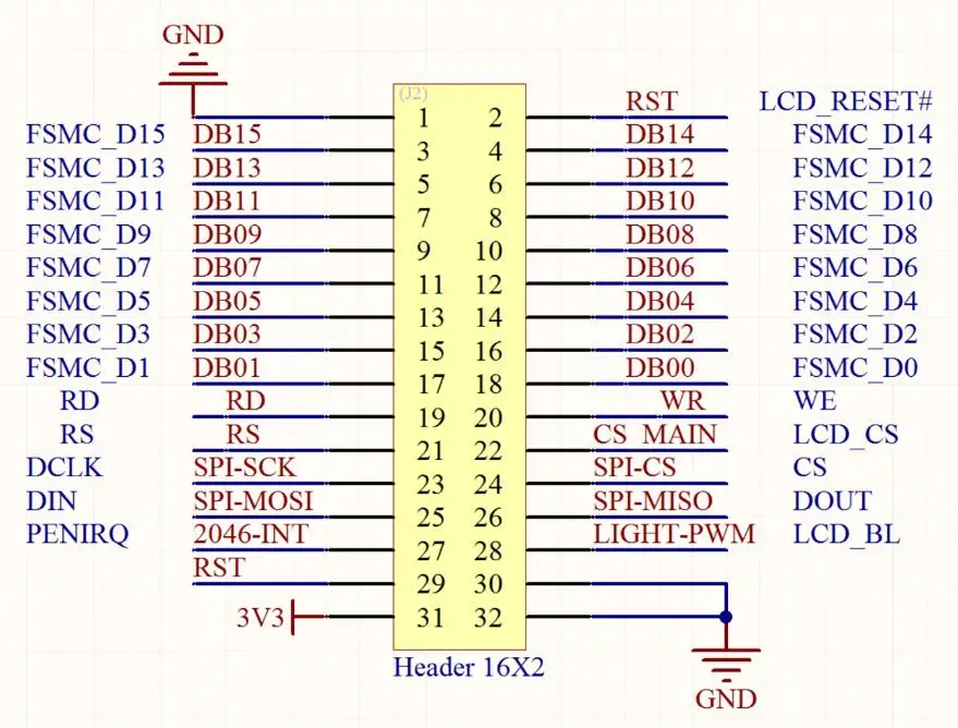
Step 1: I'm trying to implement https://github.com/jeffmer/micropython-ili9341 as per this forum thread but got a bit stuck with the pin names in https://github.com/jeffmer/micropython- ... m5stack.py which don't exactly match the ones on BLACK_F407VE ... But now that I found the diagram below, maybe I'll get further
Step 2: The idea would be to try and get the lvgl bindings to work on the BLACK_F407VE, but even the bindings for the latest version (v6) are for micropython 1.9.4. When I tried to generate my own bindings for 1.11, the unix port demos froze on me.
Compiling https://github.com/littlevgl/lv_micropy ... ee/dev-6.0 and running the demos with the unix port does work as expected and opens its own virtual SDL output under X. So maybe I just made a mistake.
Step 2.1: I will try to write some scripts to automate the README instructions, check that I get working bindings against 1.9.4 and then work my way up to 1.11. I'll contact the littlevgl people as soons as I get stuck
Step 3: driving the ili9341 using the lvgl bindings. Maybe the pure micropython solution above will be too slow for this, I don't know yet. Espressif seems to have embraced LittlevGL, so there will be code available. I'll see what I can scavenge from https://github.com/littlevgl/esp32_ili9341 for starters.
In conclusion, a lot of confused thoughts and a lot of work to be done, and I'm not sure I'll get anywhere with this, sorry! I'll keep you informed in any case.
Cheers,
John
I just got the LCD module for the BLACK_F407VE board from Aliexpress and was wondering if you had any thoughts regarding driving it from micropython (and reading the touch screen)?
And the reason why I needed the sdcard to work on BLACK_F407VE is that the filesystem is about to get really cramped!
Step 1: I'm trying to implement https://github.com/jeffmer/micropython-ili9341 as per this forum thread but got a bit stuck with the pin names in https://github.com/jeffmer/micropython- ... m5stack.py which don't exactly match the ones on BLACK_F407VE ... But now that I found the diagram below, maybe I'll get further
Step 2: The idea would be to try and get the lvgl bindings to work on the BLACK_F407VE, but even the bindings for the latest version (v6) are for micropython 1.9.4. When I tried to generate my own bindings for 1.11, the unix port demos froze on me.
Compiling https://github.com/littlevgl/lv_micropy ... ee/dev-6.0 and running the demos with the unix port does work as expected and opens its own virtual SDL output under X. So maybe I just made a mistake.
Step 2.1: I will try to write some scripts to automate the README instructions, check that I get working bindings against 1.9.4 and then work my way up to 1.11. I'll contact the littlevgl people as soons as I get stuck
Step 3: driving the ili9341 using the lvgl bindings. Maybe the pure micropython solution above will be too slow for this, I don't know yet. Espressif seems to have embraced LittlevGL, so there will be code available. I'll see what I can scavenge from https://github.com/littlevgl/esp32_ili9341 for starters.
In conclusion, a lot of confused thoughts and a lot of work to be done, and I'm not sure I'll get anywhere with this, sorry! I'll keep you informed in any case.
Cheers,
John
Re: MCUDev Black STM32F407VET6 + STM32F407ZET6 dev boards
Hi @JohnLittle, the LCD that matches this board connects via the TFT header which has a FSMC parallel interface but also has SPI pins.
I'm not sure which are wired to the display driver IC (ILI9341)...
Some of the schematics pdfs for the boards hint the SPI interface is just for touch IC (XPT2046).
The ILI9341 driver you mentioned uses the SPI interface. A different implementation than the FSMC one.
I haven't worked with the FSMC interface yet and I'm not sure if there are any other MicroPython examples using it.
TFT header pin names can be found in the schematics pdfs.
There are subtle differences between the VET6, VGT6 and ZET6 boards.
https://github.com/mcauser/BLACK_F407VE ... matics.pdf
https://github.com/mcauser/BLACK_F407ZE ... matics.pdf
Robert-hh has a driver for the touch IC:
https://github.com/robert-hh/XPT2046-touch-pad-driver
-
OutoftheBOTS_
- Posts: 847
- Joined: Mon Nov 20, 2017 10:18 am
Re: MCUDev Black STM32F407VET6 + STM32F407ZET6 dev boards
I have used the the STM32F407VET6 black with a ILI9431 TFT in 16bit parallel using the FSMC peripheral but only in C but 1 could use my library then wrap it up to be called from MP.
Here is a video of me using a ILI9431 TFT that I brought and soldered down to a breakout board then connected to the STM32F407VET6 black via the TFT header but the touch screen I connected to the ADC pins rather than uses a XT2046 IC to read the touch screen. https://www.youtube.com/watch?v=H51OzQl3BC8
Basically it involved me turning on the FSMC clock then setting all the needed pins to AF FSMC then setting just 2 FSMC registers then the ILI9431s RAM was addressable like external RAM to the MCU. I just simply set a pointer to the RAM the wrote to it.
I am not very good with using the HAL libraries so tend to just write directly to the registers using the macros in STM32F4xx.h
This is my code to setup the needed pins in AF and as FSCM.
This is the code to turn on the FSMC clock and setup the needed registers
Here is a video of me using a ILI9431 TFT that I brought and soldered down to a breakout board then connected to the STM32F407VET6 black via the TFT header but the touch screen I connected to the ADC pins rather than uses a XT2046 IC to read the touch screen. https://www.youtube.com/watch?v=H51OzQl3BC8
Basically it involved me turning on the FSMC clock then setting all the needed pins to AF FSMC then setting just 2 FSMC registers then the ILI9431s RAM was addressable like external RAM to the MCU. I just simply set a pointer to the RAM the wrote to it.
I am not very good with using the HAL libraries so tend to just write directly to the registers using the macros in STM32F4xx.h
This is my code to setup the needed pins in AF and as FSCM.
Code: Select all
//setup pins as AF
	GPIOD->MODER |= GPIO_MODER_MODER0_1 | GPIO_MODER_MODER1_1 | GPIO_MODER_MODER4_1 | GPIO_MODER_MODER5_1 | GPIO_MODER_MODER7_1 | GPIO_MODER_MODER8_1 | GPIO_MODER_MODER9_1 | GPIO_MODER_MODER10_1 | GPIO_MODER_MODER11_1 | GPIO_MODER_MODER14_1 | GPIO_MODER_MODER15_1;
	GPIOE->MODER |= GPIO_MODER_MODER7_1 | GPIO_MODER_MODER8_1 | GPIO_MODER_MODER9_1 | GPIO_MODER_MODER10_1  | GPIO_MODER_MODER11_1 | GPIO_MODER_MODER12_1 | GPIO_MODER_MODER13_1 | GPIO_MODER_MODER14_1 |  GPIO_MODER_MODER15_1;
	//setup pins as PP
	GPIOD->OTYPER &= 0b0011000001001100;
	GPIOE->OTYPER &= 0b0000000001111111;
	//set speed to 100MHz
	GPIOD->OSPEEDR |= (0b11<<(2*0)) | (0b11<<(2*1)) | (0b11<<(2*4)) | (0b11<<(2*5)) | (0b11<<(2*7)) | (0b11<<(2*8)) | (0b11<<(2*9)) | (0b11<<(2*10)) | (0b11<<(2*11)) | (0b11<<(2*14)) | (0b11<<(2*15));
	GPIOE->OSPEEDR |= (0b11<<(2*7)) | (0b11<<(2*8)) | (0b11<<(2*9)) | (0b11<<(2*10)) | (0b11<<(2*11)) | (0b11<<(2*12)) | (0b11<<(2*13)) | (0b11<<(2*14)) | (0b11<<(2*15));
	//set NO pull-up or pull-down
	GPIOD->PUPDR &= ((0b11<<(2*2)) | (0b11<<(2*3)) | (0b11<<(2*6)) | (0b11<<(2*12)) | (0b11<<(2*13)));
	GPIOE->PUPDR &= ((0b11<<(2*0)) | (0b11<<(2*1)) | (0b11<<(2*2)) | (0b11<<(2*3)) | (0b11<<(2*4)) | (0b11<<(2*5)) | (0b11<<(2*6)));
	//set other pins to AF12 i.e as FSMC pins
	GPIOD->AFR[0] = (GPIOD->AFR[0] & (0b1111<<(4*2) | 0b1111<<(4*3) | 0b1111<<(4*6))) | 0b1100<<(4*0) | 0b1100<<(4*1) | 0b1100<<(4*4) | 0b1100<<(4*5) | 0b1100<<(4*7);
	GPIOD->AFR[1] = (GPIOD->AFR[1] & (0b1111<<(4*(13-8)) | 0b1111<<(4*(12-8)))) | 0b1100<<(4*(8-8)) | 0b1100<<(4*(9-8)) | 0b1100<<(4*(10-8)) | 0b1100<<(4*(11-8)) | 0b1100<<(4*(14-8)) | 0b1100<<(4*(15-8));
	GPIOE->AFR[0] = (GPIOE->AFR[0] & ~(0b1111<<7)) | 0b1100<<(4*7);
	GPIOE->AFR[1] = 0xCCCCCCCC;
This is the code to turn on the FSMC clock and setup the needed registers
Code: Select all
	//enable RCC for FSMC
	RCC->AHB3ENR |= RCC_AHB3ENR_FSMCEN;


	//setup FSMC on Bank1 NORSRAM1
	//setup timings of FSCM
	FSMC_Bank1->BTCR[1] = FSMC_BTR1_ADDSET_1 | FSMC_BTR1_DATAST_1;
	// Bank1 NOR/SRAM control register configuration
FSMC_Bank1->BTCR[0] = FSMC_BCR1_MWID_0 | FSMC_BCR1_WREN | FSMC_BCR1_MBKEN;-
JohnLittle
- Posts: 11
- Joined: Mon Oct 08, 2018 7:10 pm
Re: MCUDev Black STM32F407VET6 + STM32F407ZET6 dev boards
Wow, thanks guys, today I learn! I also found a stm32duino thread after @mcauser mentioned FSMC.
@OutoftheBOTS_ -- Super useful video thanks, I wasn't aware there was any kind of processing involved to get an accurate position out of the touchscreen, so there you go, something else I learned!
I have played with micropython modules in C, so there's definitely some potential for a native display driver.
Talk to you soon!
-
OutoftheBOTS_
- Posts: 847
- Joined: Mon Nov 20, 2017 10:18 am
MCUDEV_DEVEBOX_F407VGT6 dev boards
When I used mcauser definitions for the STM32F407VET6 black then compiled and flashed the firmware then reboot the MCU then it showed up as a pyboard but when I use the definitions for MCUDEV_DEVEBOX_F407VGT6 then it won't compile. If I addmcauser wrote: ↑Mon Jun 03, 2019 2:17 pm@lukesky333 I put together these ones for the board:
https://github.com/mcauser/MCUDEV_DEVEBOX_F407VGT6 - 1Mbyte flash
https://github.com/mcauser/MCUDEV_DEVEBOX_F407VET6 - 512Kbyte flash
Both are 100 pin LQFP chips and it looks like larger flash is the main difference.
I guessed some of the pin numbers based on other boards by the same vendor.
Need to check them against their datasheet for this board.
I could only find a low resolution jpg. Do you have the pdf version?
Code: Select all
_sstack = _estack - 16K;There seems to be some problems with the definition of the MCUDEV_DEVEBOX_F407VGT6, have you had this port working???
-
DJShadow1966
- Posts: 60
- Joined: Sun Jun 23, 2019 4:55 am
- Location: Gateshead, Tyne and Wear
Re: MCUDev Black STM32F407VET6 + STM32F407ZET6 dev boards
Hello
Can somebody give me some pointers how to control the FSMC on this board, I have a display that interfaces to the board with no issue just really need some help of how to write to the display.
Mike
Can somebody give me some pointers how to control the FSMC on this board, I have a display that interfaces to the board with no issue just really need some help of how to write to the display.
Mike
-
OutoftheBOTS_
- Posts: 847
- Joined: Mon Nov 20, 2017 10:18 am
Re: MCUDev Black STM32F407VET6 + STM32F407ZET6 dev boards
First you need to understand how FSMC works with these screens. It utilizes the 8080 ram interface, this basically has 16 data lines and 16 address lines then a few control lines(chip select, read, write). With the TFT they don't use all the address line to address the RAM but rather uses only 1 address line connected to the RS/DC (register select/ data command select)pin.
FSMC is usually used to attached external RAM to the heap of the MCU with starting address 0x60000000 using this 8080 ram interface and allows you to address the RAM like it is part of the internal ram of the MCU. So once I have set up the FSMC pins and control registers on the MCU then I can send a command to the control resigister of the TFT if I use an address where the address line connected to the RS/DC pin is low and if I want to send data to the graphics ram of the TFT I use and address where the addressl line connected to the RS/DC pin is high
So after I have setup all the needed pins in correct AF and setup the 2 FSMC control registers then I can use the screen like this:
I had the RS/DC pin connected to address line A16 (PD11) (off memory the header connects the RS/DC pin to a different address line so you will need to change the address of LCD_REG if using the header)
Code: Select all
#define LCD_REG      (*((volatile unsigned short *) 0x60000000)) //address where A15 is low
#define LCD_RAM      (*((volatile unsigned short *) 0x60020000))  //address where A15 is high

void TFT_Init(void){
	//hardware reset
	GPIOD->ODR &= ~GPIO_ODR_ODR_12;
	HAL_Delay(200);
	GPIOD->ODR |= GPIO_ODR_ODR_12;
	HAL_Delay(120);
	//SOFTWARE RESET
	LCD_REG = 0x01;
	HAL_Delay(1000);

	//POWER CONTROL A
	LCD_REG = 0xCB;
	LCD_RAM = 0x39;
	LCD_RAM = 0x2C;
	LCD_RAM = 0x00;
	LCD_RAM = 0x34;
	LCD_RAM = 0x02;

	//POWER CONTROL B
	LCD_REG = 0xCF;
	LCD_RAM = 0x00;
	LCD_RAM = 0xC1;
	LCD_RAM = 0x30;

	//DRIVER TIMING CONTROL A
	LCD_REG = 0xE8;
	LCD_RAM = 0x85;
	LCD_RAM = 0x00;
	LCD_RAM = 0x78;

	//DRIVER TIMING CONTROL B
	LCD_REG = 0xEA;
	LCD_RAM = 0x00;
	LCD_RAM = 0x00;

	//POWER ON SEQUENCE CONTROL
	LCD_REG = 0xED;
	LCD_RAM = 0x64;
	LCD_RAM = 0x03;
	LCD_RAM = 0x12;
	LCD_RAM = 0x81;

	//PUMP RATIO CONTROL
	LCD_REG = 0xF7;
	LCD_RAM = 0x20;

	//POWER CONTROL,VRH[5:0]
	LCD_REG = 0xC0;
	LCD_RAM = 0x23;

	//POWER CONTROL,SAP[2:0];BT[3:0]
	LCD_REG = 0xC1;
	LCD_RAM = 0x10;

	//VCM CONTROL
	LCD_REG = 0xC5;
	LCD_RAM = 0x3E;
	LCD_RAM = 0x28;

	//VCM CONTROL 2
	LCD_REG = 0xC7;
	LCD_RAM = 0x86;

	//MEMORY ACCESS CONTROL
	LCD_REG = 0x36;
	LCD_RAM = 0x48;

	//PIXEL FORMAT
	LCD_REG = 0x3A;
	LCD_RAM = 0x55;

	//FRAME RATIO CONTROL, STANDARD RGB COLOR
	LCD_REG = 0xB1;
	LCD_RAM = 0x00;
	LCD_RAM = 0x18;

	//DISPLAY FUNCTION CONTROL
	LCD_REG = 0xB6;
	LCD_RAM = 0x08;
	LCD_RAM = 0x82;
	LCD_RAM = 0x27;

	//3GAMMA FUNCTION DISABLE
	LCD_REG = 0xF2;
	LCD_RAM = 0x00;

	//GAMMA CURVE SELECTED
	LCD_REG = 0x26;
	LCD_RAM = 0x01;

	//POSITIVE GAMMA CORRECTION
	LCD_REG = 0xE0;
	LCD_RAM = 0x0F;
	LCD_RAM = 0x31;
	LCD_RAM = 0x2B;
	LCD_RAM = 0x0C;
	LCD_RAM = 0x0E;
	LCD_RAM = 0x08;
	LCD_RAM = 0x4E;
	LCD_RAM = 0xF1;
	LCD_RAM = 0x37;
	LCD_RAM = 0x07;
	LCD_RAM = 0x10;
	LCD_RAM = 0x03;
	LCD_RAM = 0x0E;
	LCD_RAM = 0x09;
	LCD_RAM = 0x00;

	//NEGATIVE GAMMA CORRECTION
	LCD_REG = 0xE1;
	LCD_RAM = 0x00;
	LCD_RAM = 0x0E;
	LCD_RAM = 0x14;
	LCD_RAM = 0x03;
	LCD_RAM = 0x11;
	LCD_RAM = 0x07;
	LCD_RAM = 0x31;
	LCD_RAM = 0xC1;
	LCD_RAM = 0x48;
	LCD_RAM = 0x08;
	LCD_RAM = 0x0F;
	LCD_RAM = 0x0C;
	LCD_RAM = 0x31;
	LCD_RAM = 0x36;
	LCD_RAM = 0x0F;

	//EXIT SLEEP
	LCD_REG = 0x11;
	HAL_Delay(120);

	//TURN ON DISPLAY
	LCD_REG = 0x29;

	//dispaly inversion
	//LCD_REG = 0x21);

	//setup Memory Access Control
	LCD_REG = 0x36;
	LCD_RAM = 0b00111111;
}

void ILI9341_Set_Address(uint16_t X1, uint16_t Y1, uint16_t X2, uint16_t Y2){
	//set X min and max
	LCD_REG = 0x2A;
	LCD_RAM = X1>>8;
	LCD_RAM = X1;
	LCD_RAM = X2>>8;
	LCD_RAM = X2;

	//set y min and max
	LCD_REG = 0x2B;
	LCD_RAM = Y1>>8;
	LCD_RAM = Y1;
	LCD_RAM = Y2>>8;
	LCD_RAM = Y2;

	//write data command
	LCD_REG = 0x2C;
}

void draw_rect(uint16_t X1, uint16_t Y1, uint16_t X2, uint16_t Y2, uint16_t colour){
	ILI9341_Set_Address(X1, Y1, X2, Y2);
	for( uint32_t a = 0; a < ((X2-X1+1)*(Y2-Y1+1)); a++ ){
		LCD_RAM = colour;
	}
}

void draw_pixel(uint16_t X, uint16_t Y, uint16_t colour){
	ILI9341_Set_Address(X, Y, X, Y);
	LCD_RAM = colour;
}
-
DJShadow1966
- Posts: 60
- Joined: Sun Jun 23, 2019 4:55 am
- Location: Gateshead, Tyne and Wear
Re: MCUDev Black STM32F407VET6 + STM32F407ZET6 dev boards
Hello
Many thanks for the code, I understand the first 2 paragraphs but I seem to be confused where this code would go, does it have to compiled in the firmware ?
Regards Mike
Many thanks for the code, I understand the first 2 paragraphs but I seem to be confused where this code would go, does it have to compiled in the firmware ?
Regards Mike
-
OutoftheBOTS_
- Posts: 847
- Joined: Mon Nov 20, 2017 10:18 am
Re: MCUDev Black STM32F407VET6 + STM32F407ZET6 dev boards
As I stated above I have only used this in C and haven't yet compiled it in to the MP firmware.DJShadow1966 wrote: ↑Sat Jul 20, 2019 10:49 amHello
Many thanks for the code, I understand the first 2 paragraphs but I seem to be confused where this code would go, does it have to compiled in the firmware ?
Regards Mike
My story is this I only started to learn to program about 2.5 yrs ago and first heard of python about 2yrs ago. I started python on RPi but then discovered the limitation of real time problem with OS so moved to Micro-python but then discovered the limitations of MP and the need to be able to write some stuff in C and compile it and wrap it up to be called from MP. So I have been in the process of playing with C on STM32 MCUs and am now just starting to learn about the MP firmware so that I can port it to needed MCUs and also wrap up C functions to be able to call from MP.
To make my code be able to be called from MP you will need both this code and my code from earlier post about setting up pins in AF and setting up the FSMC registers then compile them into the firmware and wrap them up to be called from MP.